Case Study 1 – A: Vectronix PLRF25C Laser Rangefinder (with compass) under a Strong Electromagnetic Influence (Birmingham, AL)

Purpose: This blog is created to help readers a) better understand electronic compass [smartphone or rangefinder] residual azimuth deviation errors b) quantify the errors, c) model the errors, d) compensate for [correct] the errors, and e) influence the app vendors to apply the correction method within the affected smartphone app. Basically, we need to know (accurately) whether to go up / down the stream (path) we are traveling on.
Problem Statement: Can smartphone compass apps and laser rangefinders (with compass) be made more accurate and more useful?
Objective: Characterize and correct the residual compass azimuth deviation error demonstrated by a laser rangefinder with an internal electronic compass – Vectronix PLRF25C.
Observations:
- Observations A – Hypothesis
- If a measurement error is repeatable, the measurement error is predictable.
- If a measurement error is predictable, the measurement error is correctable.
- “All truth passes through three stages. First, it is ridiculed. Second, it is violently opposed. Third, it is accepted as being self-evident.”
- Observations B – Vendor Smartphone/Rangefinder Calibration (manufacturing environment)
- Today’s smartphone/rangefinder technology (especially the iPhone) is capable of producing accurate compass azimuth readings when calibrated in an environment free from external magnetic/electromagnetic interferences.
- Smartphone/rangefinder vendors (particularly Apple) offer multiple alternative procedures for calibrating (and maintaining the calibration of) the electronic compass in an environment free from magnetic/electromagnetic interferences.
- Smartphone/rangefinder vendors’ calibration procedures deal (well) with the physical arrangement of internal components and electrical currents within the device itself (in the manufacturing setting) – over which the vendors have complete control.
- Smartphone/rangefinder vendor’s calibration procedures do not deal (effectively) with the magnetic/electronic interferences existing within the user’s external operational environment – over which neither the user nor the vendors have any control.
- Smart phone vendors, smartphone app vendors, and rangefinder vendors tend to gloss over (mask) the magnitude of their electronic compass residual azimuth deviation errors.
- Observations C – Residual Compass [Azimuth] Deviation Errors (user environment)
- If your hike/ride/hunt is worth the effort, don’t compound the effort by casually accepting residual compass [azimuth] deviation errors that can be compensated (corrected).
- If your data value is worth the collection effort, don’t trash the value of your data by accepting compass [azimuth] deviation errors that can be compensated (corrected).
- If your remote facilities (target) locations are essential to your GIS database, don’t accept the rangefinder’s electronic compass (azimuth) deviation errors that can be compensated (corrected).
- Observations D – Testing & Correcting Electronic Compass Azimuth Error
- Serious compass users understand that the earth’s magnetic field strength changes with the user’s geographic location. Therefore, the author’s tests (described in this case study) are performed in two widely separated geographic locations – each experiencing completely different magnetic and/or electromagnetic environmental influences.
- Serious compass users understand that adverse environmental conditions (magnetic/electromagnetic influences) can alter the output of electronic compasses (introduce errors). Therefore, the author’s tests (described in this case study) are performed first within an area of strong magnetic / electromagnetic influences and second within an area of minimal magnetic / electromagnetic influences.
- The Vectronix PLRF25C military grade rangefinder (with an embedded electronic compass) was chosen by the author to serve as the defacto “standard” for comparison with a commercial grade electronic compass (embedded within an iPhone) providing azimuth readings (data) to multiple iPhone compass apps which may be used for personal navigation. Therefore, a range of results is to be expected (in terms of compass accuracy) to be observed; and the author’s compass azimuth error compensation method is expected to perform well in each test case.
- The author realizes that a) nothing can be done to affect the hardware [iPhone/rangefinder] vendor’s calibration effectiveness and b) nothing can be done to affect the iPhone app’s internal processing of the electronic compass output. Therefore, the author chooses to a) accept the compass azimuth errors [as is] and b) compensate the residual [after calibration] azimuth deviation errors as best can be done – a) throughout the entire 360 degree range of measurement and b) for each practical orientation of the iPhone [horizontal, portrait, and landscape].
Problem Statement Resolved
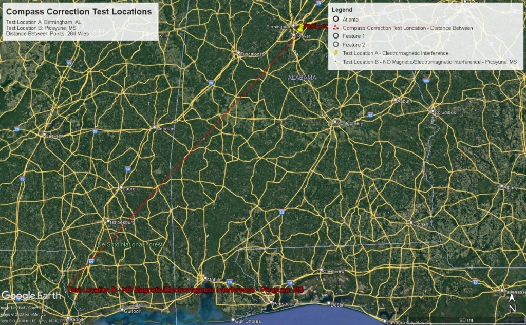
In order to accomplish the objective and resolve the problem statement, it was necessary and sufficient to determine the character of the rangefinder/smartphone [iPhone] residual [after calibration] compass azimuth deviation error by conducting actual (in-the-field) tests to a) measure the error, c) model the error, and d) determine the deviation compensation [correction] curves. Two geographically diverse test sites were chosen – separated by 264 miles.
- Test Site A was located in Birmingham, AL; and test site A (a suburban environment) experienced strong magnetic/electromagnetic influences.
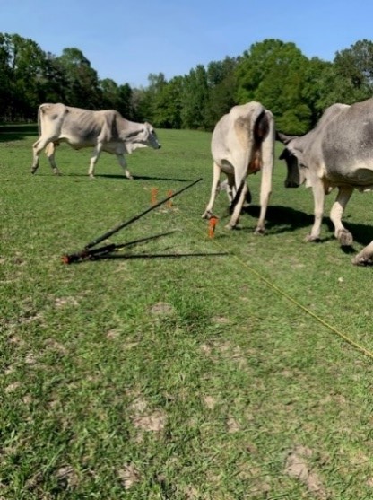
- Test Site B was located in Picayune, MS; and test site B (a 20 acre cow pasture) experienced a minimum (none) of the magnetic/electromagnetic influences.
This report (case study) demonstrates that residual compass azimuth deviation errors can be compensated [corrected] for a) a wide range of electronic compass implementations, b) a large range of distances (geographic locations), c) a diverse set of environmental influences, and d) the benefit of every-day compass users.
The two study (test) sites can be characterized (and contrasted) as follows:
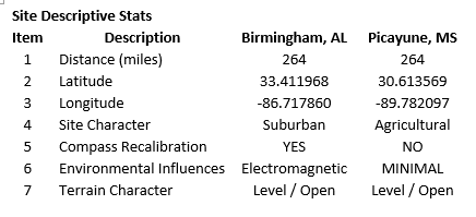
Test Site A – Birmingham, AL (suburban)
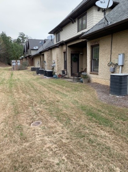
A power distribution station for 8 town homes was located within 50 feet of the test site. Eight (or more) operating 3 to 4 ton air conditioner compressors (aligned North to South) existed within 50 feet (to the East) of the rangefinder/smartphone test site. Additionally, a two-lane highway (aligned North to South) was within 150 feet to the West of the test site – with active traffic.
Test Site B – Picayune, MS (agricultural – with NO environmental influences)
At both test sites, the reference direction (True North) was established using sun position – a correct, defendable, and independent reference direction.
- True North (reference direction) was established based on the sun position relative to each test site’s geographic location on the date/time of each test.
- The Vectronix rangefinder was set to indicate azimuths relative to True North.
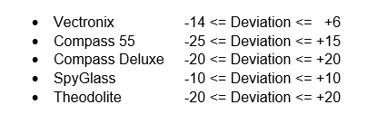
The range of residual compass azimuth deviation errors encountered (considering both test sites and all compasses tested) can be characterized as follows:
The following charts illustrate the Vectronix PLRF25C rangefinder (military grade) findings at the Birmingham, AL test site. This case study is presented first; because the rangefinder results were more consistent (and more accurate) than the results from the iPhone apps. The results from the iPhone app tests will be presented in subsequent posts.
In order to collect the necessary azimuth data, the rangefinder/tripod head was rotated into and through each of the 8 cardinal compass directions to a) collect compass azimuth readings and b) determine the deviation errors – as necessary.
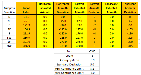
Notice that the Vectronix rangefinder is only operated in the “Portrait” orientation – normal operation. Therefore, no data is available for the “Horizontal” or the “Landscape” orientations – indicated azimuth values are set to zero. When the case studies associated with the iPhone apps are published, data for the Horizontal and Landscape orientations will be provided.
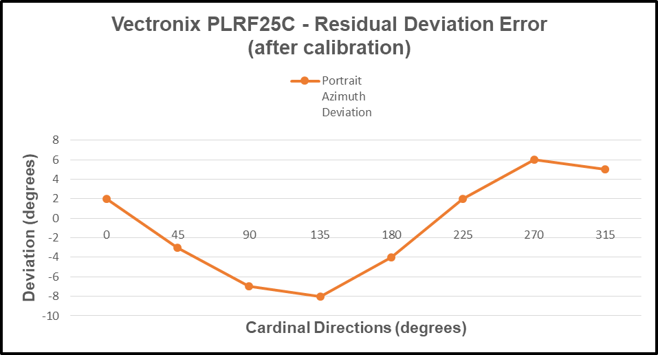
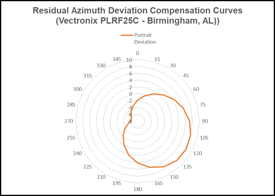
From the preceding data table, the “Portrait Indicated Azimuth” and the “Portrait Azimuth Deviation” columns are charted as follows: Residual Deviation Error.
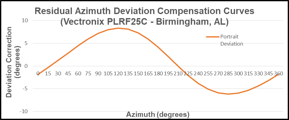
Next, the residual (azimuth) deviation error is modeled (analyzed) to produce the deviation compensation curve – as follows. The deviation compensation curve is presented in two different formats to allow the reader to truly appreciate the analysis results throughout the full 360 degrees of the compass.
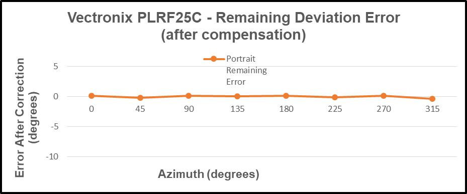
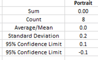
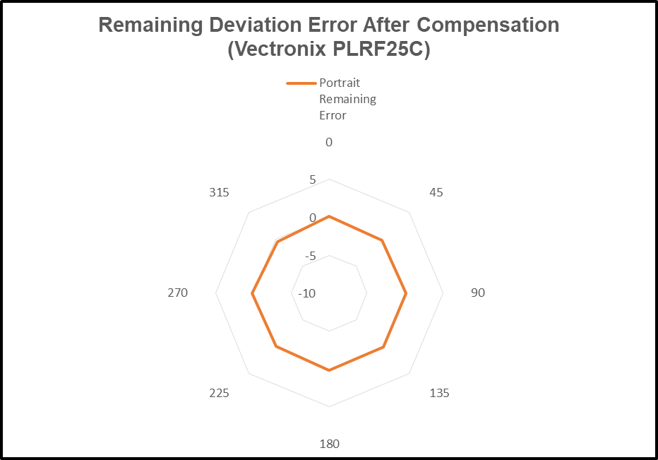
The compensated deviation errors (remaining azimuth error) for the Vectronix rangefinder are presented next. Again, two display formats are provided to strengthen the reader’s perception of the results. The error compensation method proved quite effective in this case – a significant reduction of error.
The ability to predict deviation errors of the Vectronix rangefinder was analyzed. The predicted error curve is the negative of the deviation curve; and the compensation method (again) proved quite effective. Compare the predicted error curve (solid line) with the actual measured azimuth error (orange dots).
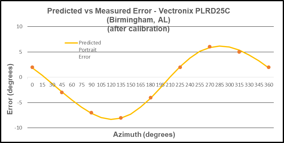
The reader should note that the Vectronix azimuth readings indicate a stable electronic compass analyzed by solid internal software. Such can be expected from a military grade instrument costing approximately $10,000.
In the next post, the Vectronix laser rangefinder will be tested at the Picayune, MS agricultural test site – with NO adverse environmental (magnetic or electromagnetic) influences. Recall that the Picayune, MS test site is located 264 miles to the Southwest of the Birmingham, AL test site. It will be interesting to note that the change in latitude had no appreciable effect on the performance of the azimuth error compensation method – even when the author elected not to re-calibrate the Vectronix rangefinder prior to that test.

Leave a comment