
Row, row, row your boat gently up / down the stream???
Introduction
Purpose (RECALL): This blog post is created to help readers a) better understand electronic compass [smartphone or rangefinder] residual azimuth deviation errors b) quantify the errors, c) model the errors, d) compensate [correct] the errors, and e) influence the app vendors to apply the correction method within their affected smartphone app. Basically, we need to know (accurately) whether to go up / down the stream (path) we are traveling on.
Goal: The goal of this blog post is to demonstrate the impact of very different environmental settings [influences] on a) the accuracy of a higher quality, commercial electronic compass [PNI Sensors – TargetPoint 3] and b) the ability of the TruPath Compass app to compensate residual (after calibration) azimuth deviation errors experienced in those different operating environments. Also, the impact of installation configuration will be demonstrated.
For more detailed information regarding the PNI Sensors – TargetPoint 3 electronic compass, visit the PNI website at:
https://www.pnicorp.com/targetpoint3/
Justification: Over the past several years, hundreds and thousands of smartphone users have complained (internet users’ forums) about their inability to use the compass apps – and rightly so. “Experts” have offered many “fixes” to resolve the issue; yet smartphone compass apps (all) have remained notoriously inaccurate.
Hypothesis: After recognizing a problem (error), if the error can be predicted, the error can be corrected (compensated).
Problem Statement: How can electronic compass azimuth errors be predicted (quantified / modeled) and then be compensated (corrected) in real world situations?
Solution Characteristics: In order for electronic compass azimuth errors to be compensated (corrected), the following statements should be true.
- The error must be quantified – throughout the entire 360 degree range of measurement – in a manner that adds minimum cost to the user in terms of a) out-of-pocket expense, b) time and effort, and c) investment in education and/or training. This means that descriptive data must be collected to quantify the error.
- Manufacturer’s recommended compass calibration procedures must be factored in (and applied) to account for the “hard iron” and “soft iron” effects attributed by the materials and component(s) arrangements within the electronic compass itself. The remaining electronic compass azimuth error to be compensated is the residual (after calibration) error resulting from environmental magnetic/electromagnetic influences – external to the electronic compass itself.
- The data collected about the compass azimuth deviation error must be “modeled” in such a way that the predicted error can be “added back to” (or subtracted from) the original erroneous azimuth readings to compensate (correct) the error(s). The compensation process must be performed in a repeatable and reliable manner over the entire 360 degree range of measurement – within the “local” environment – as may be experienced throughout a wide geographic area.
Solution Defined: The TruPath Compass smartphone app exhibits all the positive solution characteristics stated above. TruPath Compass actually fixes the problem stated above.
Background:
This post takes a look at how different environmental (external to the electronic compass itself) magnetic and electromagnetic influences affect the azimuth readings of higher-quality commercial electronic compass units. Also, this post sheds light on the affects that the installation configuration can have on the residual azimuth deviation error.
The basic data collection support equipment and procedures used in all four (4) demonstrations are identical to those used at the original Birmingham, AL test site for several prior posts. Refer to the original post/page at http://www.tru-path.org.
- True North (reference direction) was established “staked out” based on the sun position (solar azimuth) relative to the observer’s geographic location on the date/time the demonstrations were performed – a correct, defendable, and independent reference direction.
- A distant feature (target) location established a reference direction (azimuth) relative to an observer’s location. Either or both locations could be based on land survey, map, and/or GPS coordinate data.
- The Android/TruPath Compass app (and the external electronic compass device app) were set to provide azimuths relative to True North.
- The smartphone sensors (and the external electronic compass device sensors) were re-calibrated prior to initiating data collection operations.
Some controlling, fundamental facts that need to be kept in mind include:
- Residual (after calibration) compass azimuth deviation error exists; and the error magnitude varies throughout the entire 360 degree range of measurement.
- Compensation of residual (after calibration) azimuth deviation error is device (and installation) specific.
Faster, Better, Cheaper Azimuth Deviation (error) Data Collection
Typically, when collecting azimuth deviation data, the user should consider the following:
- Effort: The time required to collect azimuth deviation data should be less than 4 minutes – for each orientation (portrait, landscape, or horizontal) of the smartphone.
- Circumstances:
- On sunny days, take advantage of the shadow of a vertical object (wooden stake, light poles, edge of building, standing person, etc.) to establish a base (reference) azimuth – using TruPath Compass’ determination of the sun’s azimuth to obtain unquestionable accuracy.
- On cloudy days, establish a base (reference) azimuth with a “distant feature” using TruPath Compass’ background map. The geographical location of the distant feature can be edited (using either land survey, map, or GPS coordinates) to improve accuracy.
- Flexibility/ Accuracy/Repeatability:
- Use TruPath Compass’ augmented reality targets to collect azimuth deviation (error) data. This method does require the user to sight on the virtual target; but, usually, it is a faster (handheld) mode of operation.
- Use a camera tripod (with azimuth ring) to collect azimuth deviation (error) data by (mechanically) traversing clockwise from the base (reference) azimuth in equal 45 degree increments. This method is more steady and more accurate.
- Operation Modes: (general use or when collecting azimuth deviation data)
- Handheld (faster)
- Tripod (more accurate)
Recall the Objectives
Considering a variety of real world operating situations, this blog post will demonstrate the compensation of azimuth errors encountered when using a calibrated, higher quality electronic compass (as facilitated by the TruPath Compass app running on a smartphone) to:
- Collect residual [after calibration] azimuth deviation [error] data faster, better [easier], cheaper and
- Analyze the collected deviation data to produce a deviation compensation curve[s] – for the purpose of effectively compensating residual azimuth deviation error[s] exhibited by the electronic compass.
The Demonstration (test) Environments
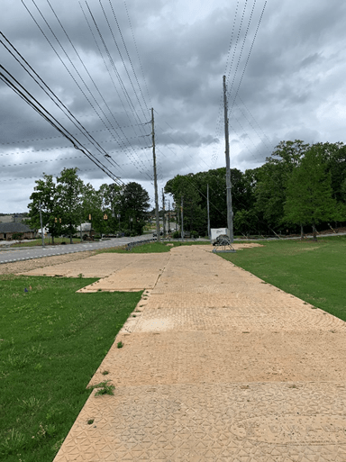
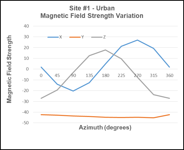
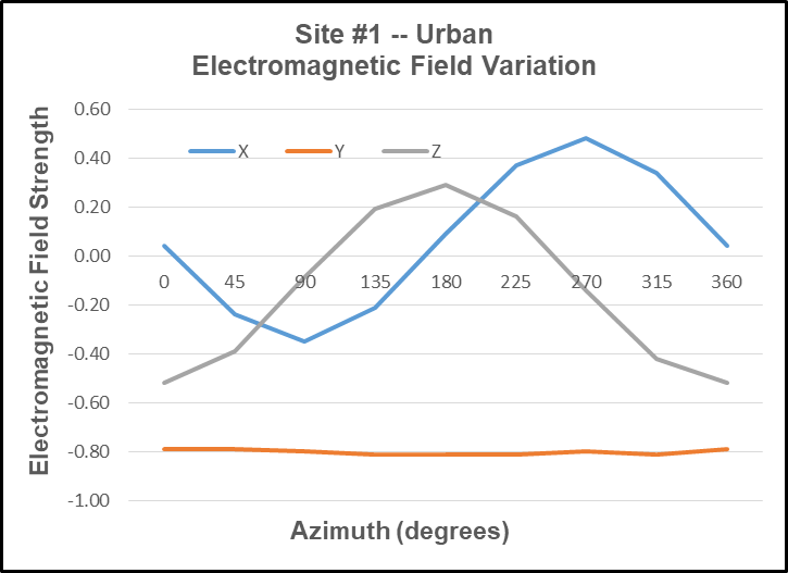
Site #1: Urban
Site #1 exists in a generally benign urban setting – common (backyard) area of an established townhome community.
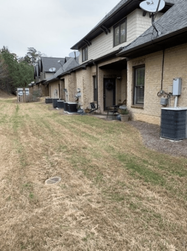
View – North
The urban site exhibits variable magnetic and electromagnetic influences including:
- An electric power distribution station is located adjacent to eight (8) townhomes.
- At least eight operating heating/cooling (heat pump) units of 3 to 4 ton capacity – aligned North/South are within 50 feet of the test site (East side).
- An active highway – aligned North/South is within 150 feet of the test site (West side).
The observer’s location was staked out within sighting distance of a vertical (pole – wooden stake) target used to cast a good shadow (sun shadow). The shadow of the vertical stake was used to establish the azimuth of the sun – and thus, the azimuth (direction) to True North – as facilitated by the TruPath Compass app. Refer to the following image.
Observer Location (GPS)
- Latitude: 33.4118433
- Longitude: -86.7178023
Smartphone in portrait orientation (South)
The tripod was capable of mounting a smartphone in either a portrait, landscape, or horizontal orientation. For these observations, only the portrait orientation was used – a) sufficient for demonstrating the mounting of various devices and b) without overwhelming the reader with voluminous repetitive information.
An external GPS unit (BadElf Surveyor – yellow) was used to increase accuracy of both the observer and the distant target geographic locations. As such, real-time GPS correction was applied to the output of the external GPS unit; and these corrected GPS position results were applied as a “mock location” for the TruPath Compass app using the NTRIP app.
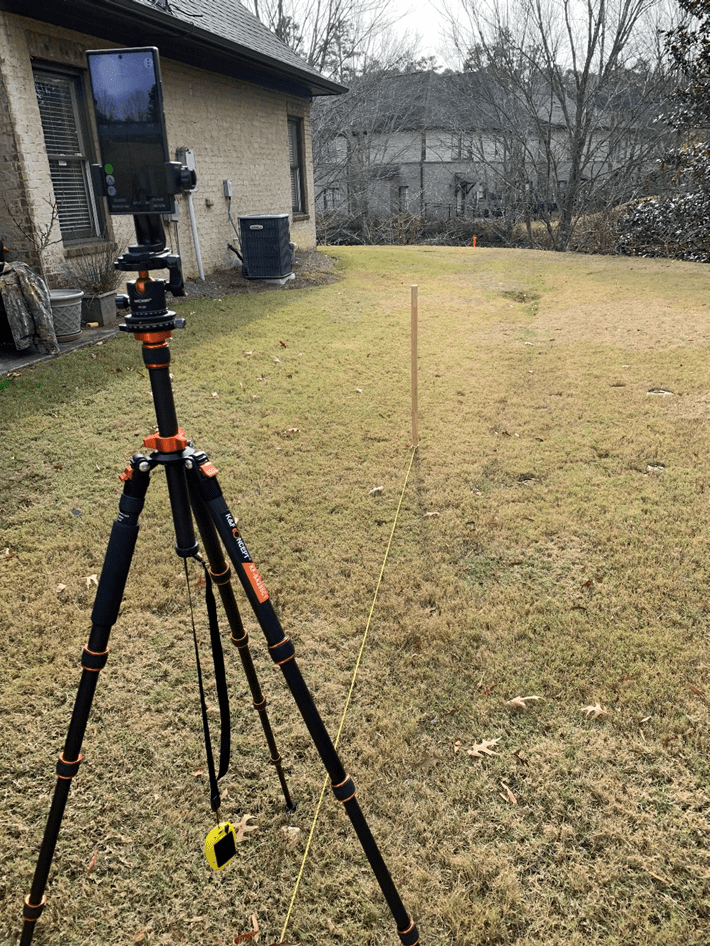
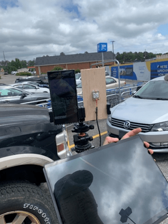
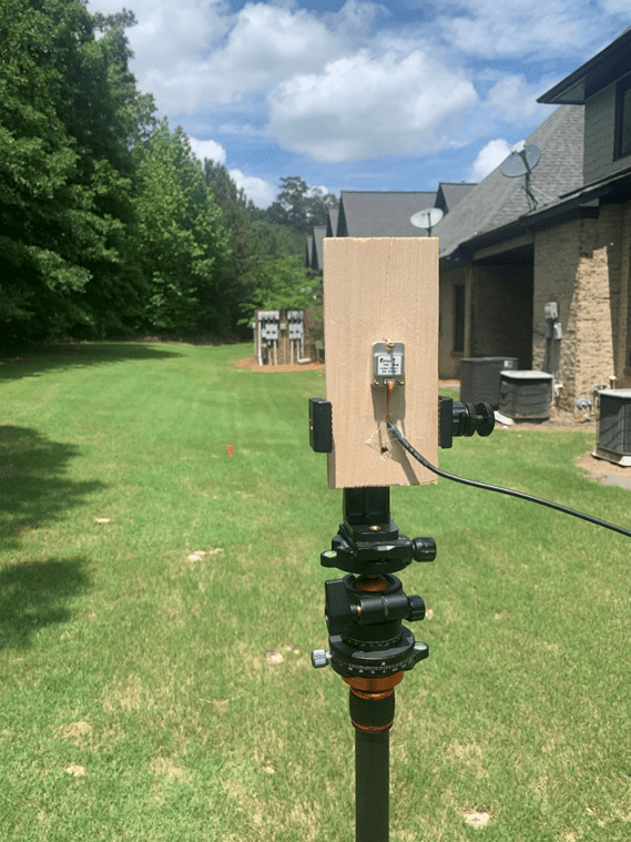
Smartphone & Electronic Compass in portrait orientation (North)
Reader Alert: The reader will note that the TargetPoint 3 electronic compass is mounted directly adjacent to an Android smartphone running the TruPath Compass app – on purpose. It is anticipated that the close proximity of the Android smartphone will significantly influence (adversely) the azimuth readings of the TargetPoint 3 compass unit. Also, it is anticipated that the residual azimuth deviation error compensation capabilities of the TruPath Compass app will correct (compensate) for this adverse influence. That’s the whole idea of these demonstrations!
Reader Alert: The reader will note that the mounting brackets used to support both the Android smartphone and the TargetPoint 3 compass unit are slightly misaligned – relative to one another. This purposeful misalignment will introduce an additional small error into the azimuth readings of the TargetPoint 3 compass. It is anticipated that the residual azimuth deviation error compensation capabilities of the TruPath Compass app will correct (compensate) for this additional adverse influence as well. Again, that’s the whole idea of these demonstrations!
The tripod (previous photo) featured an indexed azimuth ring for mechanically (reliably) controlling the azimuth direction of the smartphone and electronic compass installation – thus, there was no sighting error involved in the data collection operations.
From the observer’s location (tripod), a reference azimuth (True North) was established (staked out) using the sun’s position (solar azimuth) as a basis – as mentioned and demonstrated in previous blog posts. Notice the orange stake between the smartphone and the mounting plate for the electronic compass – as shown in the previous photo.
Distant Feature (target) Stake
In the preceding photo, the orange stake (distant feature in the background) indicates the True North azimuth from the observer’s location.
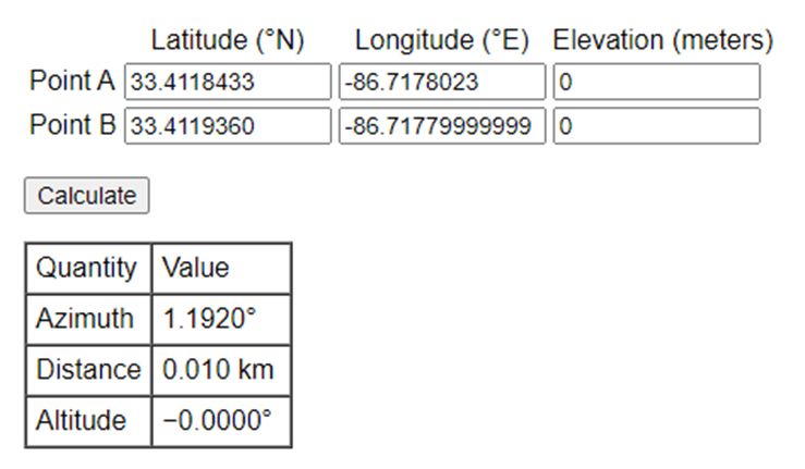
Target (orange) Stake Location (GPS)
- Latitude: 33.4119360
- Longitude: -86.7177999
Referring to the following table, the azimuth between the observation point (Point A) and the distant feature (target) point (Point B) was calculated to be 1.192 degrees – using a 64 bit computer and double precision math. When using the smartphone operating system with its inherent precision, the author might expect to experience this somewhat small azimuth error.
Moving right along, the following image depicts the author’s first calibration-with-compensation check. The smartphone’s electronic compass was calibrated; and the TruPath Compass app was used to derive the necessary and sufficient compensation parameters to correct azimuth errors being experienced by the smartphone’s electronic compass.
Notice that TruPath Compass allowed the author to place (geo-locate) a marker on the map background corresponding to the location of the orange (True North) target (stake). A marker can be placed on the map background using a Pan/Zoom capability; and that placement can be edited using either survey coordinates or GPS coordinates. The image indicates that the target marker is placed to give a reference True North azimuth from the observer’s location.
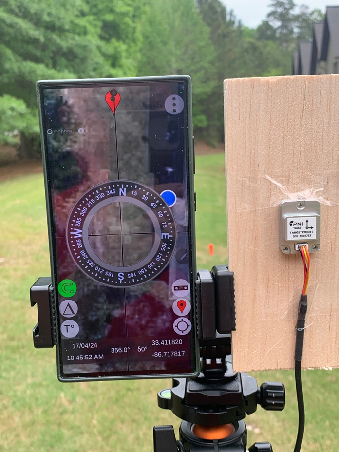
In the following photo, the “red” vertical bar directly below the “N” character (True North) indicates that TruPath Compass’ compensation is “ON” – indicated, as well, by the green (upper case delta symbol) button along the lower left side of the screen. The width/thickness of the red bar indicates the magnitude of the error compensation. The algebraic sign of the compensation value depends on which side of the vertical screen alignment line the red bar lies – left side (negative)/right side (positive). Also, the signed numeric value of the compensation angle is shown at the bottom of the image – indicated by the lower case delta symbol (-1.3 degrees).
Note: The horizontal “horseshoe” button (lower left side of screen) is “green” indicating that the state (status) of compass calibration is “good”.
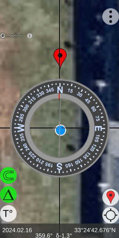
TruPath Compass “Map” Screen – Marker Location
The following image depicts the author’s second calibration check using the TruPath Compass’ augmented reality camera display (Live View) – accessed via the Menu button shown in the upper-right corner of the screen. Again, the author can be satisfied that the compass calibration is operating well. Notice that the compensation is turned “OFF” – as indicated a) by a “white” compensation button (upper case delta symbol) and b) by a compensation magnitude of zero (0) degrees at the bottom of the image.
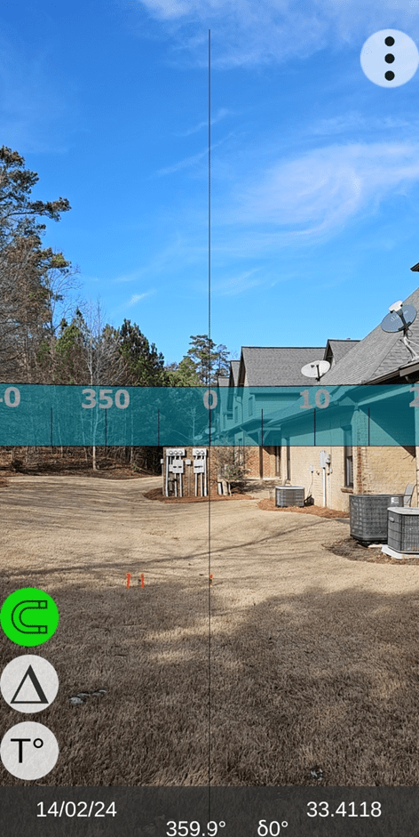
TruPath Compass “Live View” Screen (north)
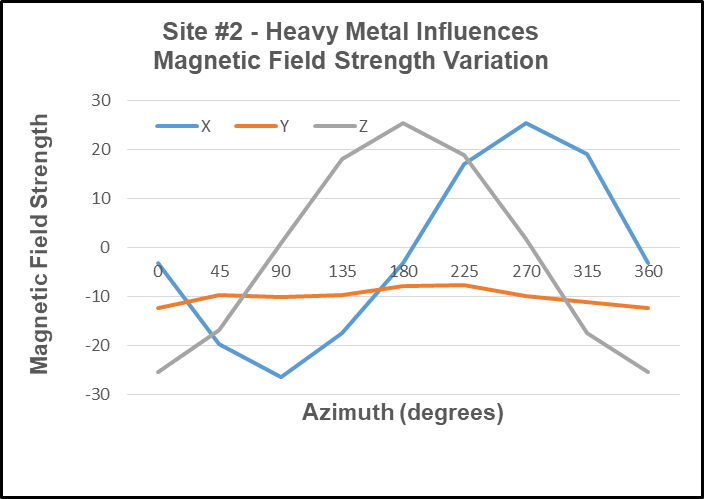
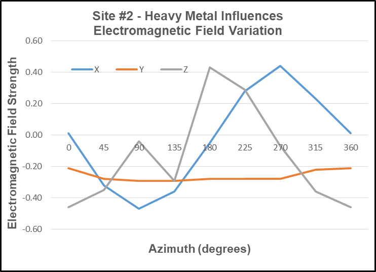
Site #2: Crowded Auto Parking Lot – heavy metal [magnetic] influence
North

Northeast
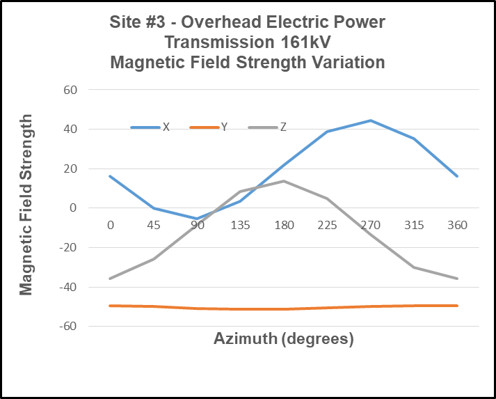
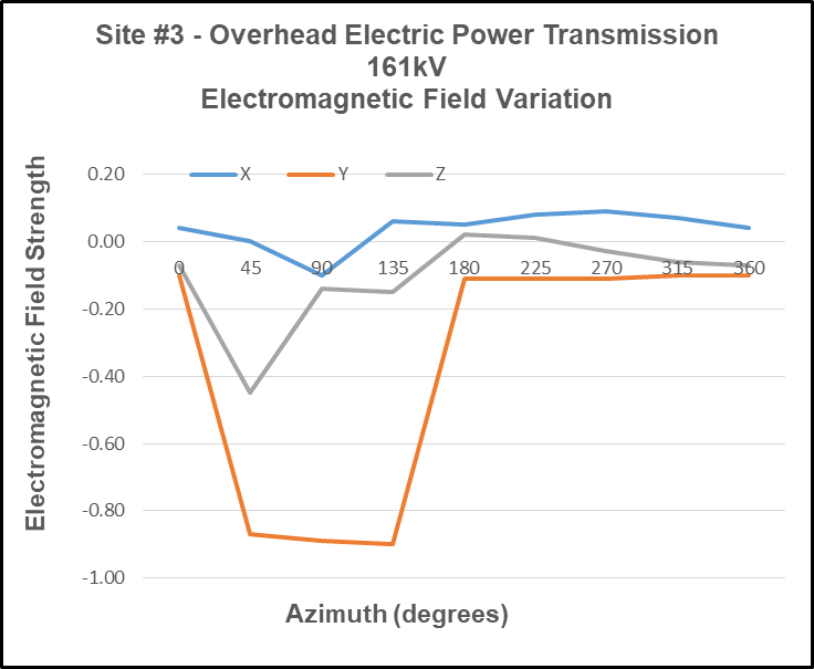
Site #3: Electric Power Transmission Corridor (161kV) – intense electromagnetic (EMF) influence
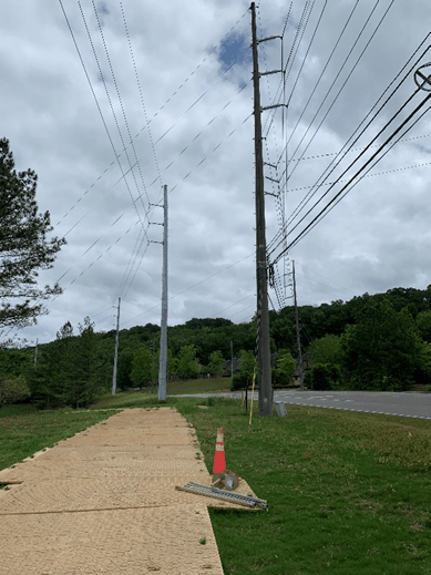
East
West
Site Environmental Characteristics
- Magnetic Characteristics
a. Site #1 – Urban
b. Site #2 – Heavy Magnetic Influences
c. Site #3 – Heavy Electromagnetic (EMF) Influences
2. Electromagnetic (EMF) Characteristics
a. Site #1 – Urban
b. Site #2 – Heavy Magnetic Influences
c. Site #3 – Heavy Electromagnetic (EMF) Influences
Test & Analysis Results
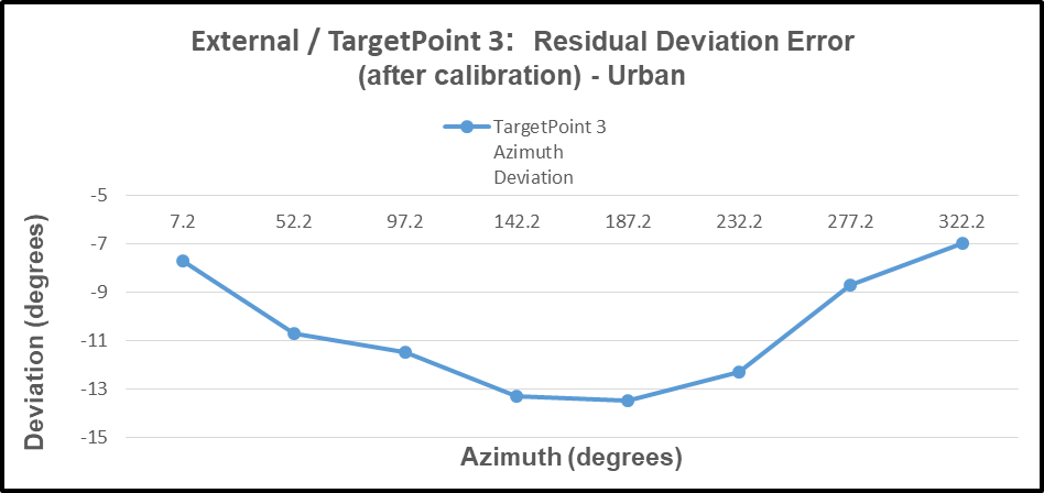
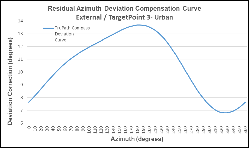
Site #1 – Urban
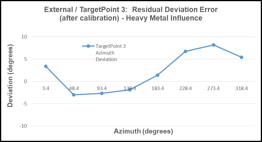
- Azimuth Deviation Data
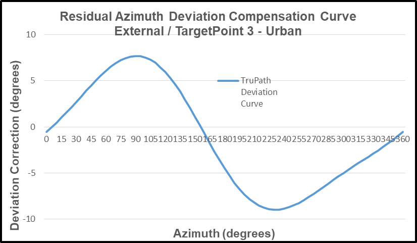
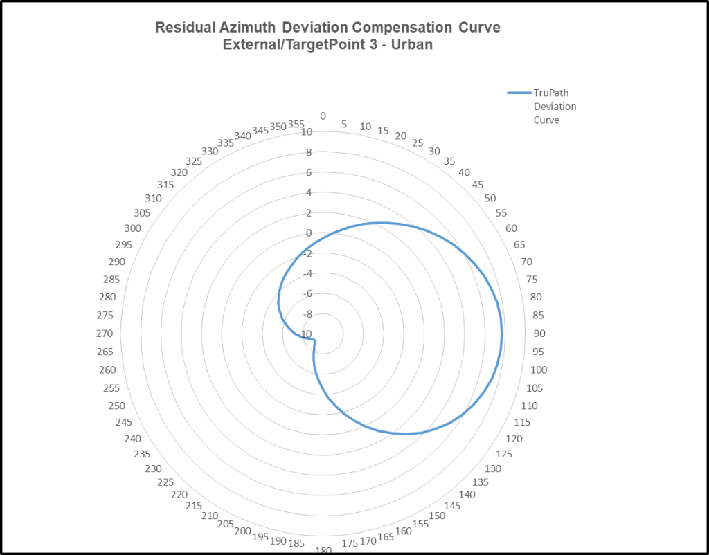
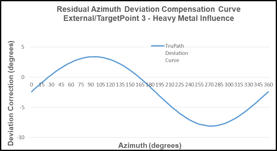
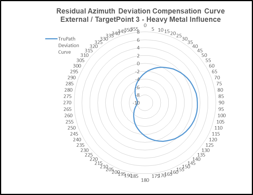
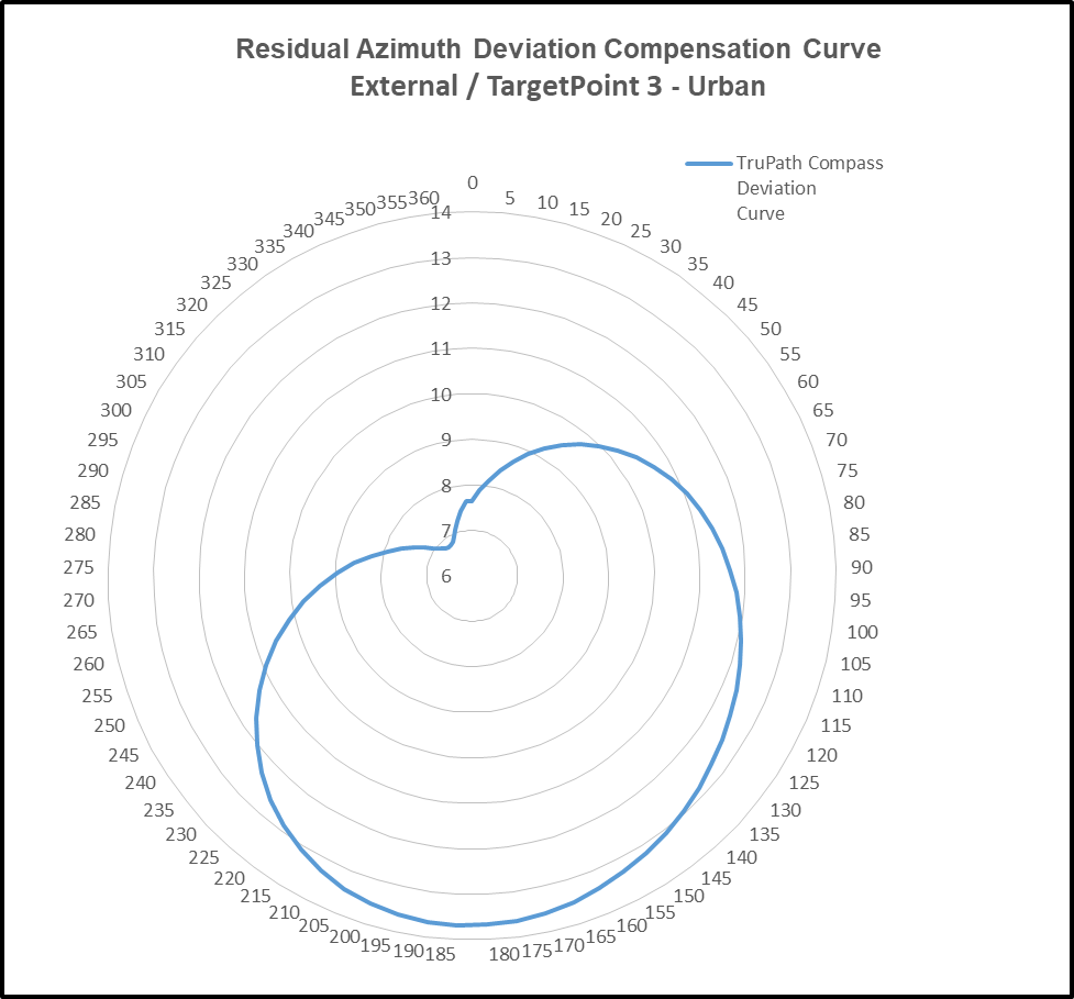
2. TruPath Deviation Compensation Curve
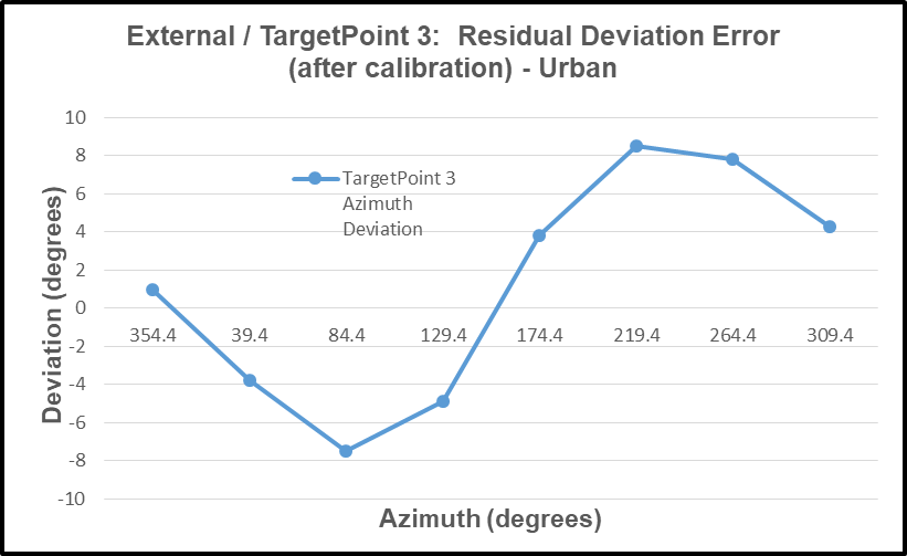
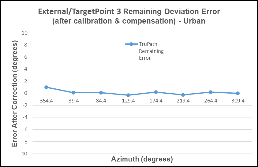
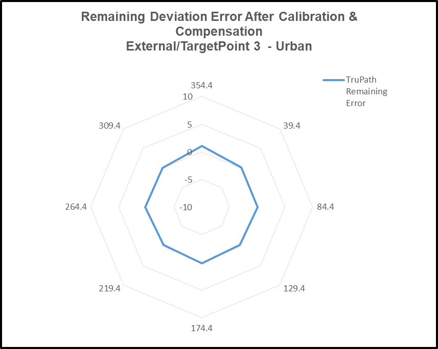
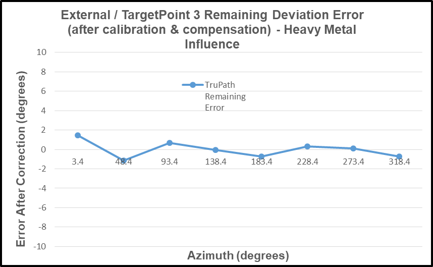
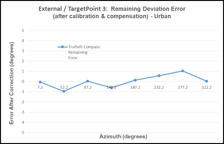
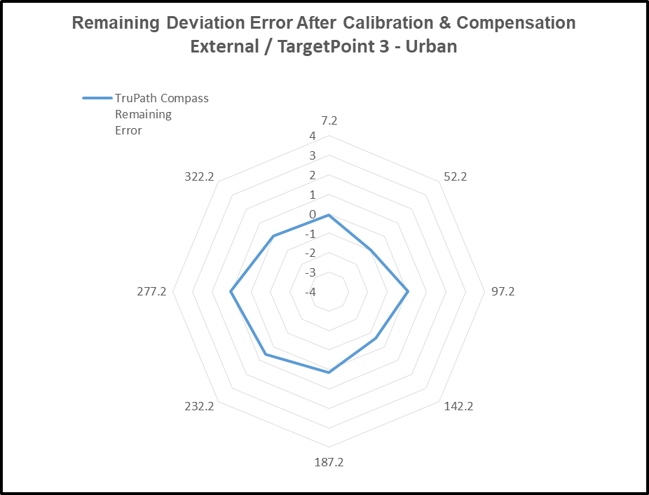
3. Remaining Deviation Error – After Compensation
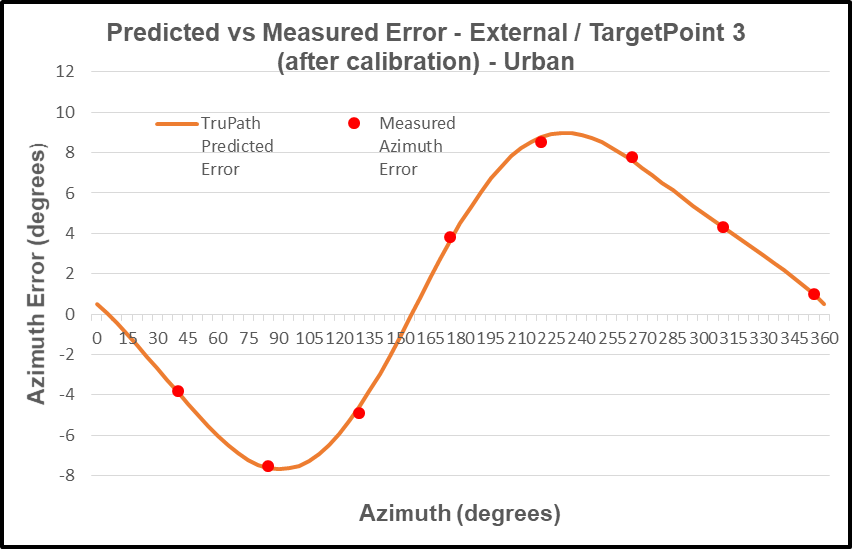
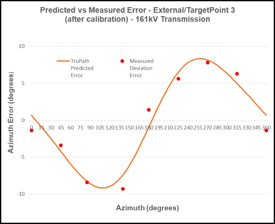
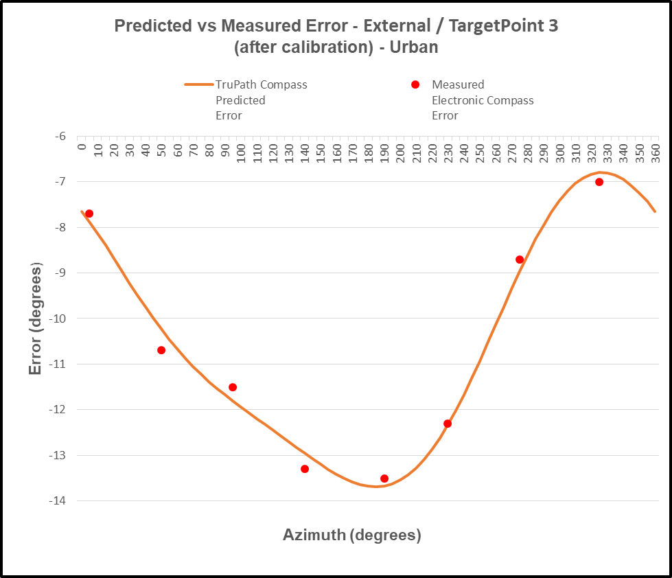
4. Predicted vs Actual Measured Deviation Error
Site #2 – Heavy Magnetic Influences (parking lot)
- Azimuth Deviation Data
2. TruPath Deviation Compensation Curve
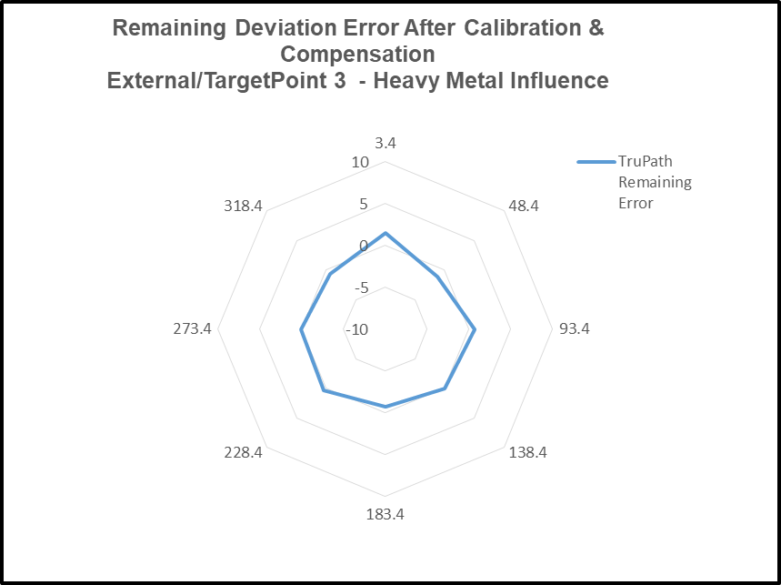
3. Remaining Deviation Error – After Compensation
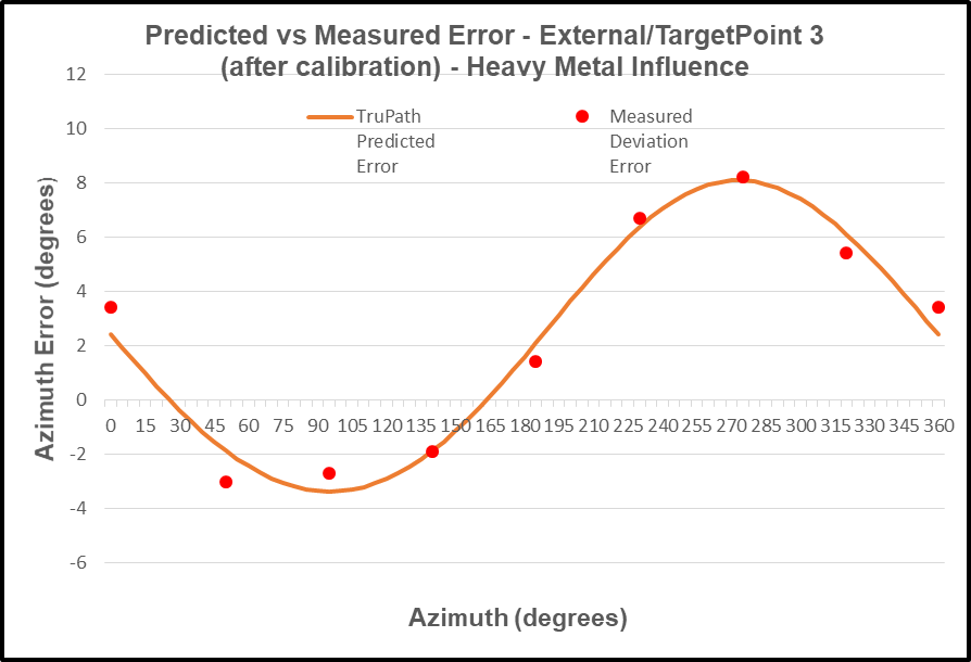
4. Predicted vs Actual Measured Deviation Error
Site #3 – Heavy Electromagnetic (EMF) Influences (electric power transmission line)
- Azimuth Deviation Data
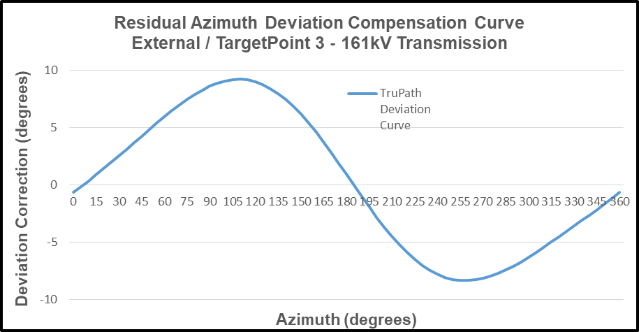
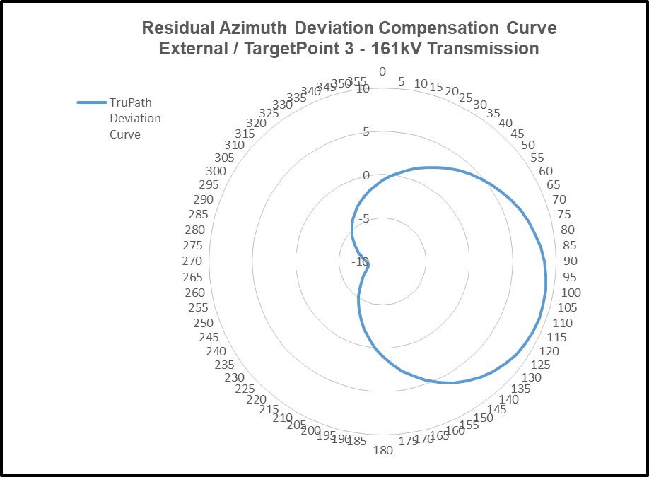
2. TruPath Deviation Compensation Curve
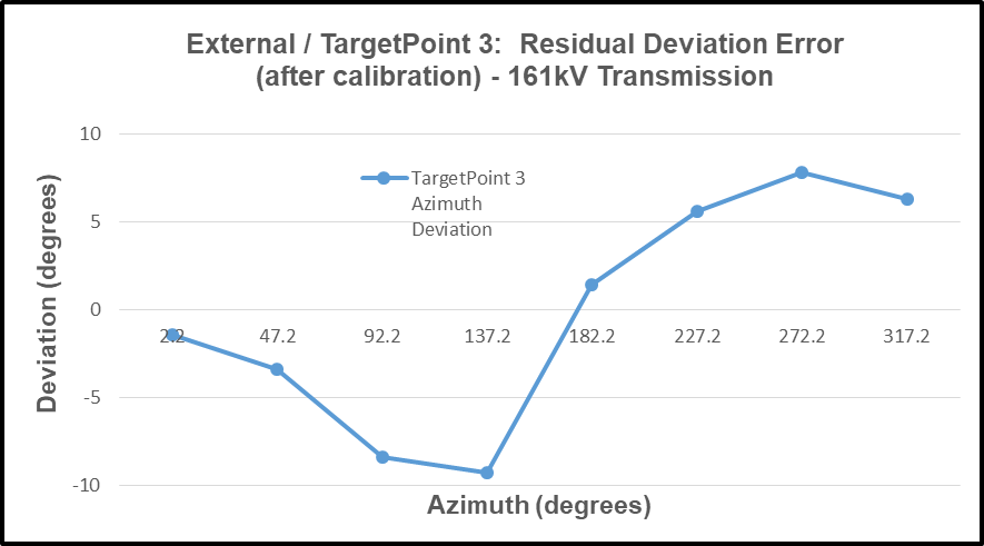
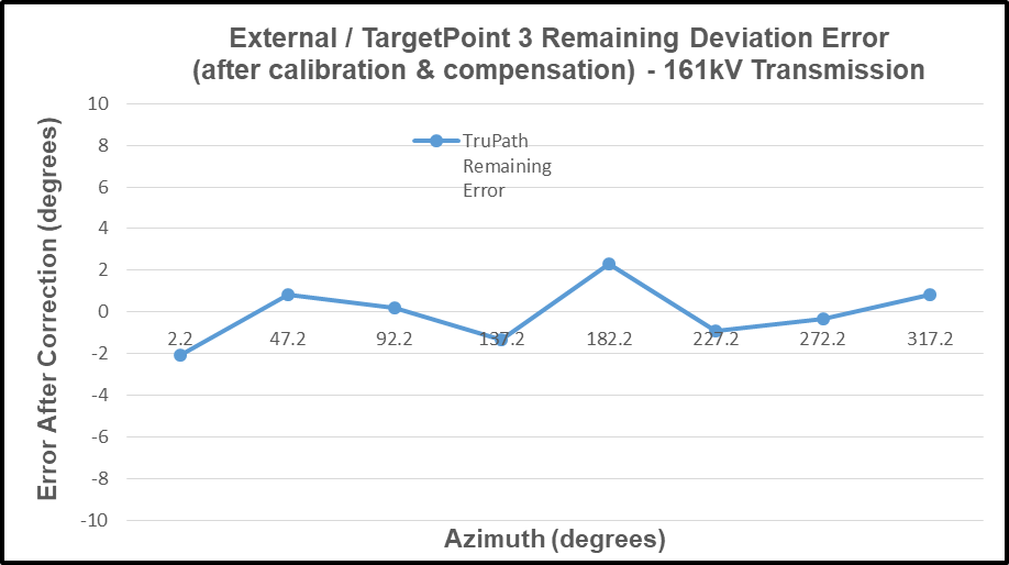
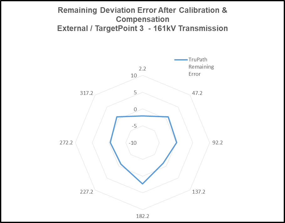
3. Remaining Deviation Error – After Compensation
4. Predicted vs Actual Measured Deviation Error
Installation Configuration Considerations
As previously mentioned, the residual compass azimuth deviation error experienced by the electronic compass is highly dependent on the installation configuration – device specific. Recall the side-by-side mounting of the smartphone and the electronic compass in the first demonstration – the urban environment (Site #1).
To demonstrate sensitivity to the installation configuration, the smartphone was relocated approximately six (6) feet away from the electronic compass.
Electronic Compass (minimal external influences)
- No phone – within about 6’ (running TruPath Compass)
- No watch
- No car keys
- No eye glasses (or sunglasses)
- Etc.
Test Results: (minimum external influences)
Site #1 – Urban
- Azimuth Deviation Data
2. TruPath Deviation Compensation Curve
3. Remaining Deviation Error – After Compensation
4. Predicted vs Actual Measured Deviation Error
User Value Proposition
Conclusion: As observed in each of the four (4) test cases described above, the necessary and sufficient combination of a) the manufacturer’s recommended calibration procedure and b) TruPath Compass’ compensation techniques produced superior azimuth error compensation results – the customer’s own intent.
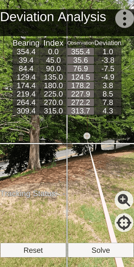
TruPath Deviation Data Collection Screen (Site #1) – minimum external influences
Note: To facilitate the deviation data collection effort, TruPath makes use of “augmented reality” technology. Note the circular “target” just below the data table – at the end of a white linear shaft that extends back to the user location.
Conclusion: Electronic compass users [customers] can a) use the TruPath Compass smartphone app to collect residual azimuth deviation [error] data from any electronic compass employed in a wide variety of real-world operating conditions – in a faster, better (easier), and cheaper way – and b) receive five [5] TruPath Compass azimuth error compensation coefficients [correction parameters] immediately – to be shared with the compass manufacturer’s software [or the user’s own software] to compensate the azimuth errors being encountered.
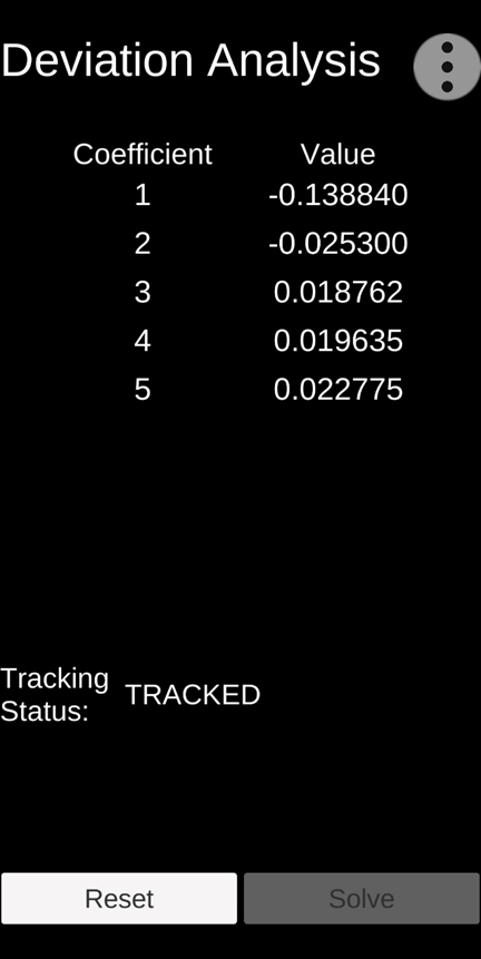
TruPath Deviation Coefficient Screen (Site #1)
Preview
Future blog posts will delve into the features of the TruPath Compass app.

Leave a comment