(app introduction)

Row, row, row your boat gently up / down the stream???
Purpose (RECALL): This blog post is created to help readers a) better understand electronic compass [smartphone or rangefinder] residual azimuth deviation errors b) quantify the errors, c) model the errors, d) compensate [correct] the errors, and e) influence the app vendors to apply the correction method within the affected smartphone app. Basically, we need to know (accurately) whether to go up / down the stream (path) we are traveling on.
GOAL:
The goal of this blog post is to provide a descriptive narrative about the capabilities and features of our new smartphone compass app – soon to be released on both the Apple store and the Google Play store.
Justification (RECALL): Over the past several years, hundreds and thousands of smartphone users have complained (internet users’ forums) about their inability to successfully use the compass apps – and rightly so. “Experts” have offered many “fixes” to resolve the issue; yet smartphone compass apps (all) have remained notoriously inaccurate – and for good reason. Residual (after calibration) azimuth deviation errors really do exist – resulting from local environmental magnetic/electromagnetic influences.
Hypothesis (RECALL): After recognizing a problem (error), if the error can be predicted, the error can be corrected (compensated).
Problem Statement (RECALL): How can electronic compass azimuth errors be predicted (quantified / modeled) and then be compensated (corrected) in real world situations?
Solution Characteristics (RECALL): In order for electronic compass azimuth errors to be compensated (corrected), the following statements should be true.
- The error must be quantified – throughout the entire 360-degree range of measurement – in a manner that adds minimum cost to the user in terms of a) out-of-pocket expense, b) time and effort, and c) investment in education and/or training. This means that descriptive data must be collected to quantify the error.
- Manufacturer’s recommended compass calibration procedures must be factored in (and applied) to account for the “hard iron” and “soft iron” effects attributed by the materials and component(s) arrangements within the electronic compass itself. The electronic compass azimuth error to be compensated is the residual (after calibration) error resulting from environmental magnetic/electromagnetic influences – external to the electronic compass itself.
- The data collected about the compass azimuth deviation error must be “modeled” in such a way that the predicted error can be “added back” (subtracted) from the original erroneous azimuth readings to compensate (correct) the error(s) – in a repeatable and reliable manner over the entire 360-degree range of measurement – within the local environment, over a wide geographic area.
Solution Defined: The new smartphone app (soon to be released) exhibits all the positive solution characteristics stated above. The new compass app actually fixes the problem stated above – electronic compass azimuth error.
Background:
For some time, this blog has strived to a) prove the existence of residual (after calibration) compass azimuth deviation errors and b) prove the existence of a practical approach (solution) for correcting (compensating) those errors. Throughout the existence of this blog, the author has referred to this solution as the Tru-Path Compass app. Now, as the release of the app is at hand, insurmountable trademark (product name) issues have surfaced requiring that the name of the compass app be changed to AugView Compass. The new name a) reflects the use of augmented reality technology for ease-of-use and b) is directly related to the software developer – AugView of Auckland, New Zealand.
The Narrative:
Has anyone ever been frustrated by smartphone Compass apps that a) claim to be accurate, b) turn out to be hopelessly inaccurate; and/or c) don’t work at all in certain device orientations? More than likely, the answer to the previous question is “YES”.
The question / response (above) is what motivated the author(s) to create the Augview Compass app – a compass app that a) is more accurate, b) works in all orientations, and c) provides both a map view and an Augmented Reality (AR) view (live camera view) for ease of use. The accuracy improvement is achieved first by measuring the compass deviation error (after calibration error) for each primary orientation (portrait, horizontal, landscape [left], and landscape [right], as may be required) and second by applying a suitable correction (compensation) capability to overcome observed azimuth errors.
Augview Compass is a high-accuracy smartphone compass application, supporting:
- Compass deviation error measurement & correction
- Map navigation compass azimuths,
- Augmented reality (Live View) compass viewing,
- Map marker tracking (find-my-spot), and
- Observations in all device orientations (it works).
Compass (sensors)
A smartphone (or tablet) incorporates a variety of sensors that can be used to determine device location, orientation, and/or the way the device is moving. The compass (device) orientation is determined using a combination of these sensors – the magnetometer, accelerometer, and gyroscope.
- The magnetometer is the primary sensor used to detect magnetic fields – functioning as a digital compass. It measures the Earth’s magnetic field in three dimensions (X, Y, Z axes) and helps determine the direction relative to Magnetic North. The reader should note that the Earth’s magnetic field is relatively weak. Magnetometers used in smartphones demonstrate high levels of signal noise, when compared with the Earth’s magnetic field strength. Also, magnetometers are susceptible to stray magnetic/electromagnetic fields being generated both a) within the device and b) in the local operating environment(s). Furthermore, temperature changes can significantly impact magnetometer sensitivity. To reduce noise in the magnetometer output(s), software filters with smoothing algorithms are used often. To improve magnetometer accuracy, the output(s) from the accelerometer and gyroscope are integrated with the magnetometer using a technique known as sensor integration.
- The accelerometer measures the device’s linear acceleration in three dimensions (X, Y, and Z axes). When stationary, the accelerometer measures the force/direction of gravity. By detecting the orientation of the device relative to the ground (for example, if it’s tilted), the accelerometer can determine the angle of the device in relation to the vertical axis. The accelerometer’s data is crucial for correcting the compass heading, especially when the device is tilted – tilt compensation.
- The gyroscope measures the rate of rotation around the three orientation axes. It provides information about the angular motion of the device – thus helping to track its orientation and movements more accurately. This data helps to a) smooth out the changes in orientation and b) provide more precise tracking of the device’s orientation.
Using the output(s) from the three sensors mentioned above (along with filtering algorithms and sensor fusion) a bearing relative to Magnetic North can be determined programmatically.
The Magnetic North Pole is a point on the surface of Earth’s Northern Hemisphere at which the planet’s magnetic field points vertically downward. The magnetic north pole moves over time. As of 2024, the location of the magnetic north pole is 86° N, 142° East. Modelling predicts that by 2025, the location of the magnetic north pole will have drifted to 138° East (same latitude).
True North refers to the geographic North Pole, the point at the top of the Earth’s rotation axis where all lines of longitude converge. This is the northern point of the Earth’s axis of rotation. True North is a fixed point located at 90° North latitude. True North is essential for mapping and GPS systems use, as it provides a consistent reference for determining direction regardless of magnetic variations.
The angular difference between Magnetic North and True North is called magnetic declination. This angle varies depending on where an observer might be located on the Earth’s surface; and it must be accounted for to convert magnetic compass bearings to bearings relative to True North. In addition, because the north and south magnetic poles move, magnetic declination at a fixed point on the earth’s surface changes over time. Fortunately, there are formulae and web sites that can provide the declination angle value for any given date and geographic location. The magnetic declination angle allows us to convert from a bearing relative to Magnetic North to a bearing relative to True North. To indicate whether a bearing is relative to True North or Magnetic North, we use the symbols °T or °M, respectively.
Compass Calibration
The operating system running on smartphone device(s), allows the user to Calibrate the magnetometer – to help reduce azimuth error(s) and to compensate for issues such as:
- Sensor Drift: Over time, the performance of the magnetometer can drift due to changes in temperature, humidity, and other environmental factors.
- Local Magnetic Interference: Nearby magnetic materials (e.g., buildings, vehicles, metal objects) can create local magnetic fields that distort the magnetometer’s measurements.
- Sensor placement and phone manufacturing issues can lead to variations in sensor output – resulting in a) each axis having different sensitivity, b) axes not being orthogonal, and/or c) axes not being correctly oriented relative to the phone screen.
To help reduce magnetometer issues, phone manufacturers recommend a) rotating the device about each axis and/or b) rotating the device in a figure of 8 motion. The author(s) recommend a systematic approach (in-app tutorial), by which a device user can:
- Face north (or south) to be parallel with the earth’s magnetic field flux lines (to access maximum and minimum magnetic field strengths);
- Rotate the device slowly (360° in about 4 seconds) about each axis twice; and
- Hold the device flat and rotate about the vertical axis twice.
Calibration should be performed regularly, and especially after charging the device or leaving it near other electrical devices. Also, it’s important to calibrate the magnetometer after travelling in a vehicle, especially EVs and PHEVs.
Compass Deviation Error
Even after calibration, the magnetometers within all phones and tablets (that the author[s] have tested) have exhibited a significant degree of compass azimuth error which varied as the device(s) have been rotated through 360 degrees. In almost all cases, the error observed at any specific orientation was reproducible (within a small margin). That is, rotating the device to align with a distant fixed object generally yielded the same result (within a small margin) for multiple, repeated measurements.
Define the difference between an observed (measured) bearing (relative to True North) and the actual (reference) True North bearing (e.g., calculated using accurate GNSS surveyed locations or using the sun’s azimuth) as the Deviation Error. Hypothesis: a) if a compass user can measure the deviation error for a few/several angles as the device is rotated through a full 360-degree range of measurement, b) the user [or the app] can calculate a correction function that will provide error correction/compensation for any observed bearing angle through a full 360-degree range of measurement.
Observation: The magnitude of Deviation Errors has often been observed to be in the range (+/-)15°; but the author’s research has exposed examples in excess of (+/-)20°.
More specifically, with regard to the measurement of deviation error, the Augview Compass app:
- Provides a mechanism to easily measure the deviation error at 45° increments throughout 360-degrees of measurement.
- Facilitates the user’s determination of an accurate reference azimuth orientation – achieved using either:
- The sun’s shadow (Knowing the user’s geographical location, observation date, and time-of-day, the app calculates the sun’s azimuth accurately.)
- A distant object (e.g., a significant structure on the horizon – the position of which is automatically determined from the map – is provided by the app’s “map” screen.)
Simply stated, the difference between the observed bearing and the true bearing is the deviation error – associated with each individual observation. To facilitate collection of multiple successive deviation error measurements, the AugView Compass app a) makes use of surface tracking technologies to control device (smartphone) rotations in equal, accurate 45° increments; and b) with each successive rotation, enables the user to collect “true” bearing and “observed” bearing measurements – the difference being the observed deviation error.
This process (to collect multiple successive deviation error measurements) does not require the use of a tripod to achieve acceptable results – although use of a tripod may provide a more consistent result. The measurements need to be collected in a well-lit, relatively-flat area with sufficient surface texture for surface tracking technologies (ARKit & ARCore) to work well. The user will not be able to measure the deviation error in poorly lit areas or at night. Also, it is important that the user a) keep the centre of the device screen aimed at or below the horizon and b) use surface tracking technologies at relatively short ranges, for best results.
GNSS tracking
GNSS refers to the Global Navigation Satellite System. The GNSS “system” is a set of satellites (put into orbit by multiple countries) that each broadcast information that can be used by a receiver device to determine the device’s geographic location. There are currently 6 constellations of satellites, totaling approximately 125 satellites:
- GPS (USA)
- GLONASS (Russia)
- Galileo (European Union)
- BeiDou (China)
- NavIC (India)
- QZSS (Japan)
The Augview Compass app needs to “know” the user’s device location in order to:
- calculate the magnetic declination at the observer’s location and
- display the observer’s location on the app’s map screen.
Multiple Screens
The application provides multiple screens, each with a unique function/purpose:
- Map display
- Displays a map background with compass rose overlay.
- Supports “capture” of a Point of Interest (Pin) – “smart marker”
- Display direction from observer toward Pin – “find my spot”
- Enable/Disable GNSS tracking
- Enable/Disable device “level” indicators
- Display magnetometer calibration status
- Enable/Disable deviation error correction
- Toggle between “True North” & “Magnetic North” bearings
- Display current “digital bearing”, “deviation correction”, ”latitude & longitude”
- Live View (AR) display
- Displays an Augmented Reality compass over the live “camera” video
- Supports camera zoom function
- Displays calibration status
- Enable/Disable deviation error correction
- Toggle “True North” & “Magnetic North” bearings
- Displays “digital bearing”, “deviation correction”, “latitude & longitude”
- Calibration
- Describes recommended calibration procedure
- Provides a link to video tutorial
- Deviation
- Deviation error collection “setup” screen
- Deviation error data collection screens
- Supports collecting deviation error for user’s device or an external device
- Supports use of sun azimuth or distant object for the initial observation
- Supports collection of deviation error for portrait, landscape and horizontal orientations
- Settings
- Settings related to units and display formats
- Current corrections file – notification
- Current declination value
- App version – notification
- Enable/Disable Tutorial
- Corrections
- Import corrections data
- Export corrections data
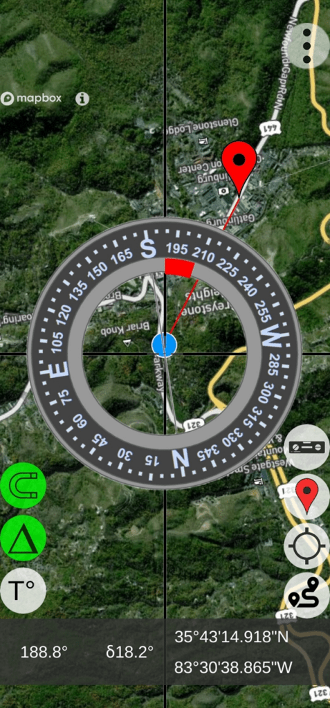
AugView – Map Screen (Note: “Red” arc indicating 18.2 degree error correction being applied.
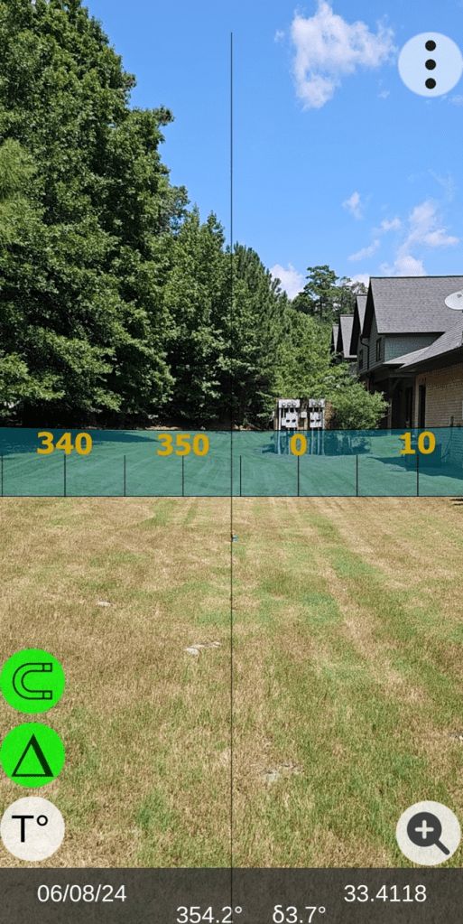
AugView – Live View Screen
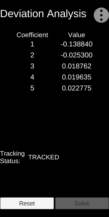
Deviation Analysis Results (error compensation coefficients)
User Value Proposition (Conclusions)
Conclusion: The manufacturer’s recommended calibration procedures should be followed.
Conclusion: The AugView Compass app a) augments the manufacturer’s recommended calibration procedures and b) compensates residual (after calibration) compass azimuth deviation errors caused by local environmental magnetic/electromagnetic influences.
Conclusion: The “experts” who publish reviews of smartphone compass apps need to extend their “analysis” methods to include an evaluation/determination of the compass app’s accuracy (or lack thereof).
Conclusion: Smartphone compass users [customers] can a) use the AugView Compass smartphone app to collect residual azimuth deviation [error] data from any electronic compass employed in a wide variety of real-world operating conditions – in a faster, better (easier), and cheaper way – and b) receive the AugView Compass azimuth error compensation coefficients [correction parameters] immediately – to be shared with the compass app’s vendor [or the user’s own software] to compensate the azimuth errors being encountered locally.

Leave a comment