
Row, row, row your boat gently up / down the stream???
Purpose (RECALL): This blog post is created to help readers a) better understand electronic compass [smartphone or rangefinder] residual azimuth deviation errors b) quantify the errors, c) model the errors, d) compensate [correct] the errors, and e) influence the app vendors to apply the correction method within the affected smartphone app. Basically, we need to know (accurately) whether to go up / down the stream (path) we are traveling on.
Goal: The goal of this blog post is to demonstrate how to “fix” smartphone compass azimuth errors using a distant geographic feature (water tower).
Justification (RECALL): Over the past several years, hundreds and thousands of smartphone users have complained (internet users’ forums) about their inability to successfully use the compass apps – and rightly so. “Experts” have offered many “fixes” to resolve the issue; yet smartphone compass apps (all) have remained notoriously inaccurate – and for good reason. Residual (after calibration) azimuth deviation errors really do exist – resulting from local environmental magnetic/electromagnetic influences.
Hypothesis (RECALL): After recognizing a problem (error), if the error can be predicted, the error can be corrected (compensated).
Problem Statement (RECALL): How can electronic compass azimuth errors be predicted (quantified / modeled) and then be compensated (corrected) in real world situations?
Solution Characteristics (RECALL): In order for electronic compass azimuth errors to be compensated (corrected), the following statements should be true.
- The error must be quantified – throughout the entire 360-degree range of measurement – in a manner that adds minimum cost to the user in terms of a) out-of-pocket expense, b) time and effort, and c) investment in education and/or training. This means that descriptive data must be collected to quantify the error.
- Manufacturer’s recommended compass calibration procedures must be factored in (and applied) to account for the “hard iron” and “soft iron” effects attributed by the materials and component(s) arrangements within the electronic compass itself. The electronic compass azimuth error to be compensated is the residual (after calibration) error resulting from environmental magnetic/electromagnetic influences – external to the electronic compass itself.
- The data collected about the compass azimuth deviation error must be “modeled” in such a way that the predicted error can be “added back” (subtracted) from the original erroneous azimuth readings to compensate (correct) the error(s) – in a repeatable and reliable manner over the entire 360-degree range of measurement – within the local environment, over a wide geographic area.
Solution Defined: The new AugView Compass smartphone app (now available on Apple store and Google Play store) exhibits all the positive solution characteristics stated above. This new compass app actually fixes the problem stated above – electronic compass azimuth error.
Background:
A remote site (free from external magnetic/electromagnetic influences) was located that allowed the identification of a “distant feature” (water tower) at a range quite sufficient to perform an AugView Compass “Deviation Analysis” resulting in a minimum remaining azimuth error.

Water Tower (distant feature [target])
Three smartphones used a) the same “distant feature” and b) their own individual AugView Compass app deviation data collection procedure to collect their own set of azimuth deviation (error) data.
- Apple iPhone SE (recent purchase)
- Apple iPhone 12 MAX (4 years old)
- Samsung 23S MAX (2 years old)
Each of the three smartphones’ compass sensors were recalibrated (on site) prior to executing their own AugView Compass Deviation Analysis.
Each of the three smartphones experienced a significant improvement in compass azimuth accuracy.
The Narrative:
The distant water tower location was to be used simultaneously with the (AugView Compass) observer GPS location to determine a reference (accurate) azimuth direction – for subsequent deviation data collection.
To help locate the distant feature on the Map screen, the user can access the Live View screen (below) to obtain an initial (uncorrected) azimuth toward the distant object – about 53 degrees.
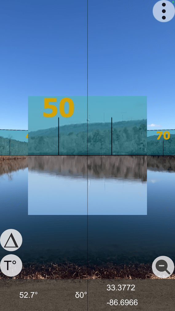
Live View (with zoom feature activated)
Note the water tower in the zoomed feature at 52.7 degrees – in the above image.
The user has the option to locate a distant feature on the Map screen (crosshairs); as AugView Compass supports the placement of a “smart” marker at that location – the smart marker’s location being defined by the map coordinates (latitude/longitude) of the identified map feature. Be sure to click “OK” to accept the located distant target.
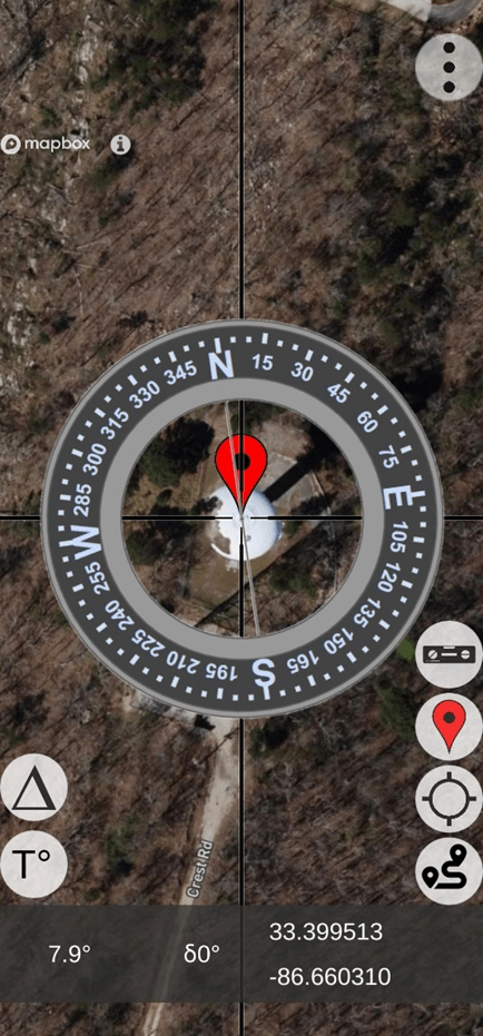
Located Distant Feature (note the map coordinates)
At this point, the user would a) click on the GPS button to “center” the Map display on the user’s location and b) display of the direction vector from the user’s location toward the distant feature (target) – “find my spot”. Also, this technique can be used to find the user’s vehicle in a crowded parking lot – see the image below – with a vector pointing from the user’s “current” location toward the “previously placed” smart marker.
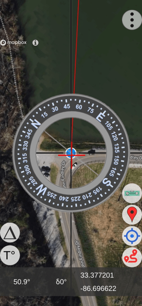
Find-my-Spot (lower right button activates the position vector)
Using this technique, some small error will remain due to the phone’s internal GPS error; however, this small error still provides excellent results compared to the original azimuth error being experienced.
- User Location (from previous image)
- Latitude: 33.377201
- Longitude: – 86.696622
- Distant Target Location
- Latitude: 33.3995114
- Longitude: – 86.6603104
The azimuth and the distance from the observer to the distant target were computed (offline verification) as:
- Azimuth = 53.86 degrees (notice the [red line] azimuth indicated in the image above)
- Distance = 13,759.68 feet (2.606 miles)
At this point, the user would access the menu and select the “Deviation Analysis” screen to setup the parameters for the deviation data collection operation – which follows.
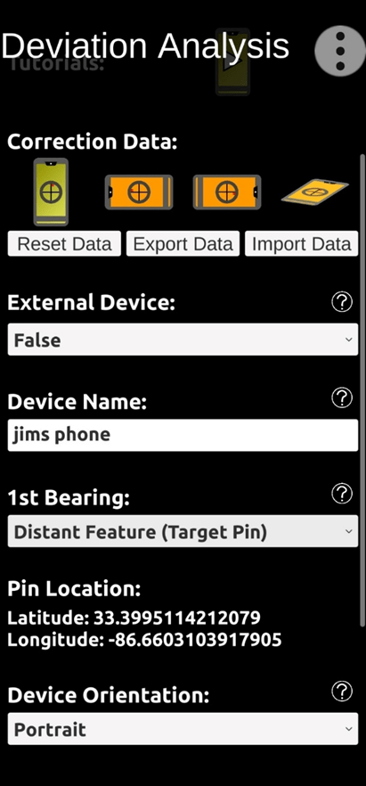
Deviation Analysis Setup Screen (note distant feature map coordinates)
Under “Correction Data” (image above), notice four phone orientation symbols – Portrait, Landscape (left), Landscape (right), and Horizontal. The Portrait symbol is green indicating that correction data has already been collected from a previous location – for the Portrait orientation; and that’s OK. When we collect fresh deviation data from the current site for the Portrait orientation, the older data will be replaced.
The orange color of the remaining symbols indicates that NO correction data exists (at all) for those orientations.
Since we will be collecting deviation data for the user’s phone (Portrait orientation), there is NO “External” device – like another phone or rangefinder.
The device we are using is “Jim’s Phone” – a Samsung 23S MAX smartphone.
We will be taking the first (reference) bearing on the identified distant feature – as noted in the “1st Bearing” setting. Other options are available to take the first reference bearing based on the sun’s positions – either a) looking towards the sun aligning with the shadow of a vertical object or b) looking away from the sun. Note that the distant object’s map coordinates are provided for reference in the setup screen.
The device orientation will be “Portrait”. Note: The device compass errors encountered for each orientation will be different.
After all the necessary parameters have been selected, the user will scroll to the bottom of the Deviation Analysis setup screen and click on the “Next” button to start the deviation data collection process. Collect the first deviation data point (targeting the water tower) by touching the active screen.
The next image shows that the first (water tower) and second (augmented reality target) deviation data points have been collected. The user clicked on the “Next” button to collect the second data record. Now, the white arrow indicates the direction the user should rotate (himself with the phone) to encounter the next (3rd) augmented reality target.
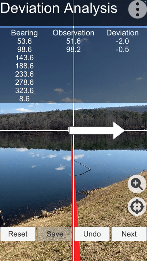
Augmented Reality Targets (for deviation data collection)
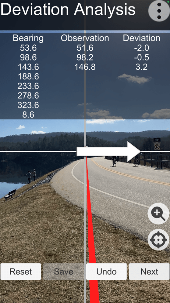
Third (3rd) Deviation Data Point Collected
Continue to collect all eight (8) deviation data points – consecutively. After the last deviation data point is collected, the user should click the “Save” button. The save operation a) completes the deviation data collection operations and b) calculates the azimuth error correction parameters necessary and sufficient to correct the phone’s azimuth errors. Note: The entire deviation data collection operation takes about 3 to 4 minutes to complete.
At this point in time, the user can take “corrected” azimuth readings (as required) in the general vicinity of the lake – and beyond, as long as no obvious magnetic / electromagnetic influences are noticed.
After the Deviation Analysis was performed for all three phones (at the remote site), each phone was relocated to other new (different) locations and pointed in the direction of approximately 53 degrees to determine their relative error corrections at the new sites – with different magnetic/electromagnetic influences. Recall that the calculated azimuth from the observer (lake) location to the distant target location was 53.68 degrees – at the remote site location.
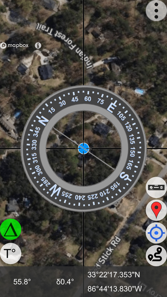
Apple iPhone SE (different user location)
Note: At azimuth = 55.8 degrees, an error of +0.4 degrees is being corrected.
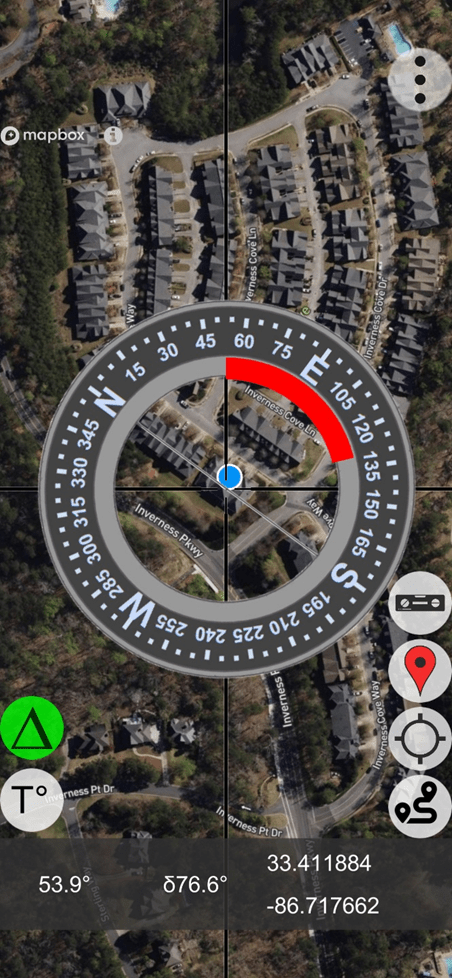
Apple iPhone 12 MAX (different user location)
Note: At azimuth = 53.9 degrees, an error of +76.6 degrees is being corrected.
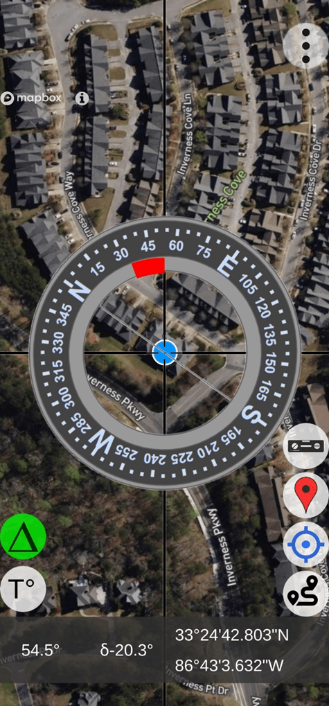
Samsung 23S MAX (different user location)
Note: At azimuth = 54.5 degrees, an error of -20.3 degrees is being corrected.
As depicted by the three images above, all three smartphones experienced different azimuth errors in their new different locations; and all three smartphones applied their own unique azimuth error correction parameters derived at the same remote (lake) location. It’s easy to see that each set (smartphone) of error correction parameters is “device dependent”. Each smartphone experienced a different unique azimuth error in its new environment; yet each corrected that error based on unique deviation correction parameters derived at the same previous remote location – the lake.
User Value Proposition (Conclusions)
Conclusion: The manufacturer’s recommended calibration procedures should be followed.
Conclusion: The AugView Compass app a) augments the manufacturer’s recommended calibration procedures and b) compensates residual (after calibration) compass azimuth deviation errors caused by local environmental magnetic/electromagnetic influences.
Conclusion: The AugView Compass azimuth error correction results are “device dependent”.
Conclusion: The “experts” who publish reviews of smartphone compass apps need to extend their “analysis” methods to include an evaluation/determination of the compass app’s accuracy (or lack thereof).
Conclusion: Smartphone compass users [customers] can a) use the AugView Compass smartphone app to collect residual azimuth deviation [error] data from any electronic compass employed in a wide variety of real-world operating conditions – in a faster, better (easier), and cheaper way – and b) receive the AugView Compass azimuth error compensation coefficients [correction parameters] immediately – to be shared with the compass app’s vendor [or the user’s own software] to compensate the azimuth errors being encountered locally.

Leave a comment