
Row, row, row your boat gently up / down the stream???
Purpose (RECALL): This blog post is created to help readers a) better understand electronic compass [smartphone or rangefinder] residual azimuth deviation errors b) quantify the errors, c) model the errors, d) compensate [correct] the errors, and e) influence the app vendors to apply the correction method within the affected smartphone app. Basically, we need to know (accurately) whether to go up / down the stream (path) we are traveling on.
Goal: The goal of this blog post is to demonstrate how to “fix” a military rangefinder’s compass azimuth errors using a distant geographic feature (water tower) with the AugView Compass app.
Justification (RECALL): Over the past several years, hundreds and thousands of smartphone users have complained (internet users’ forums) about their inability to successfully use the compass apps – and rightly so. “Experts” have offered many “fixes” to resolve the issue; yet smartphone compass apps (all) have remained notoriously inaccurate – and for good reason. Residual (after calibration) azimuth deviation errors really do exist – resulting from local environmental magnetic/electromagnetic influences.
Hypothesis (RECALL): After recognizing a problem (error), if the error can be predicted, the error can be corrected (compensated).
Problem Statement (RECALL): How can electronic compass azimuth errors be predicted (quantified / modeled) and then be compensated (corrected) in real world situations?
Solution Characteristics (RECALL): In order for electronic compass azimuth errors to be compensated (corrected), the following statements should be true.
- The error must be quantified – throughout the entire 360-degree range of measurement – in a manner that adds minimum cost to the user in terms of a) out-of-pocket expense, b) time and effort, and c) investment in education and/or training. This means that descriptive data must be collected to quantify the error.
- Manufacturer’s recommended compass calibration procedures must be factored in (and applied) to account for the “hard iron” and “soft iron” effects attributed by the materials and component(s) arrangements within the electronic compass itself. The electronic compass azimuth error to be compensated is the residual (after calibration) error resulting from environmental magnetic/electromagnetic influences – external to the electronic compass itself.
- The data collected about the compass azimuth deviation error must be “modeled” in such a way that the predicted error can be “added back” (subtracted) from the original erroneous azimuth readings to compensate (correct) the error(s) – in a repeatable and reliable manner over the entire 360-degree range of measurement – within the local environment, over a wide geographic area.
Solution Defined: The new AugView Compass smartphone app (now available on Apple store and Google Play store) exhibits all the positive solution characteristics stated above. This new compass app actually fixes the problem stated above – electronic compass azimuth error.
Background:
A remote site (free from external magnetic/electromagnetic influences) was located that allowed the identification of a “distant feature” (water tower) at a range quite sufficient to perform an AugView Compass “Deviation Analysis” resulting in a minimum remaining azimuth error.

Water Tower (distant feature [target])
A Samsung 23S MAX smartphone (operating the AugView Compass app) was used to
- Establish the map coordinates of a distant target;
- Establish the “corrected” azimuth from the observation point to the distant target;
- Record the deviation (azimuth error) data collected using the military rangefinder; and
- Determine the deviation correction parameters used to compensate the military rangefinder compass azimuth errors.
A military grade laser rangefinder (Vectronix PLRF25C – $10,000) was used to
- Establish the slant range from the observation point to the distant target;
- Establish the inclination angle from the observation point to the distant target; and
- Establish the observed compass azimuth (True) from the observation point to the distant target.
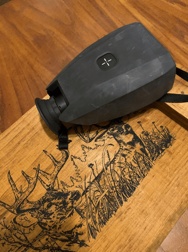
Vectronix PLRF25C Rangefinder (military grade)
Narrative: Rangefinder Deviation Data Collection
The distant water tower location was to be used (offline verification) with the (AugView Compass) observer GPS location to determine a reference (accurate) azimuth direction for subsequent deviation data collection.
To help locate the distant feature on the Map screen (AugView Compass), the user can access the Live View screen (below) to obtain an initial (uncorrected) azimuth toward the distant object – about 53 degrees.
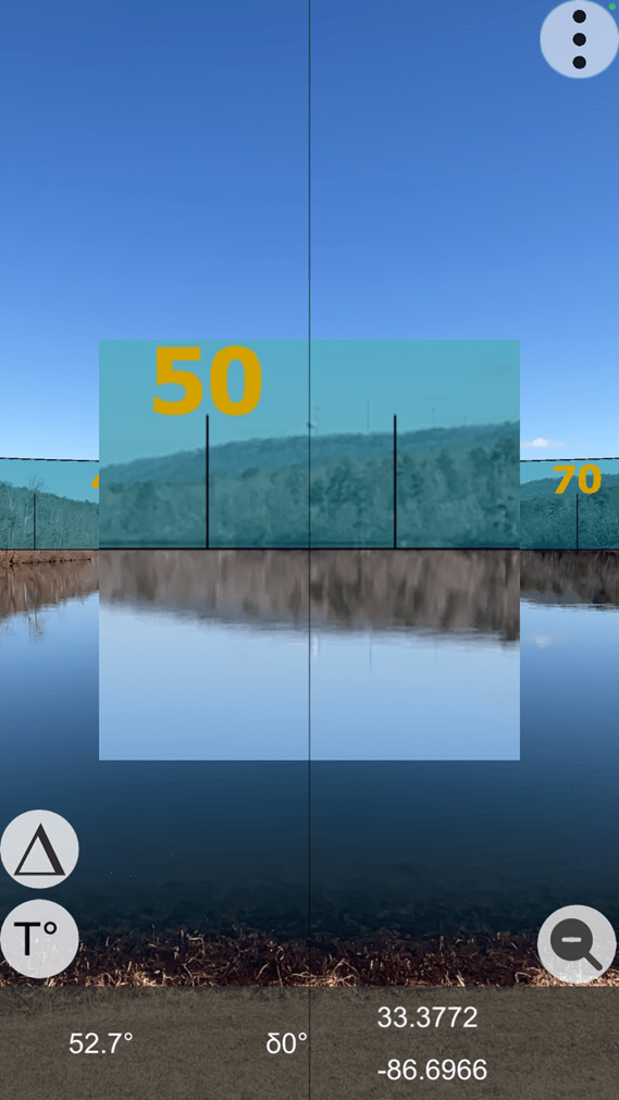
Live View Screen (with zoom feature activated)
Note the water tower in the zoomed feature at 52.7 degrees – in the above image is used as a basis for scrolling the Map screen background of the AugView Compass app to identify and locate the water tower.
The user has the option to locate a distant feature on the Map screen (crosshairs); as AugView Compass supports the placement of a “smart” marker at that location – the smart marker’s location being defined by the map coordinates (latitude/longitude) of the identified map feature. Be sure to click “OK” to accept the located distant target.
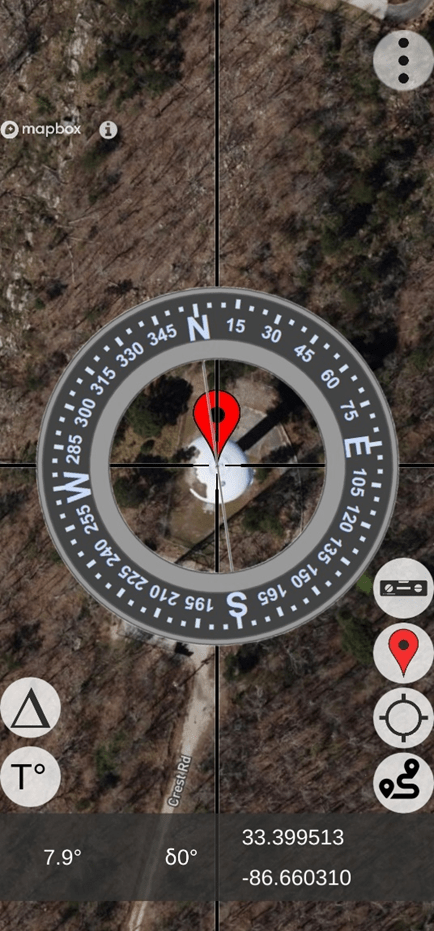
Located Distant Feature (note the map coordinates)
At this point, the user would a) click on the GPS button to “center” the Map display on the user’s location and b) display of the direction vector from the user’s location toward the distant feature (target) – “find my spot”. Also, this technique can be used to find the user’s vehicle in a crowded parking lot – see the image below – with a vector pointing from the user’s “current” location toward the “previously placed” smart marker.
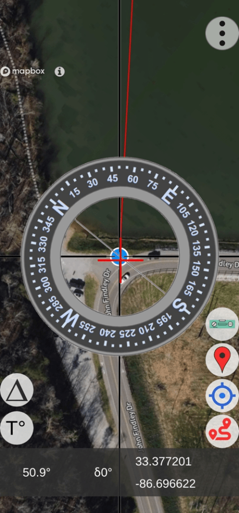
Find-my-Spot (lower right button activates the position vector)
Using this technique, some small error will remain due to the phone’s internal GPS error; however, this small error still provides excellent results compared to the original azimuth error being experienced.
- User / Observation Location (from previous image)
- Latitude: 33.377201
- Longitude: – 86.696622
- Distant Target Location
- Latitude: 33.3995114
- Longitude: – 86.6603104
The azimuth and horizontal distance from the observer to the distant target were computed (offline verification) as:
- Azimuth = 53.86 degrees (notice the [red line] azimuth indicated in the image above)
- Horizontal Distance = 13,759.68 feet (2.606 miles)
Note: The rangefinder measured the slant distance to the target as 13,731 feet.
At this point, the user would access the menu and select the “Deviation Analysis” screen to setup the parameters for the deviation data collection operation – which follows.
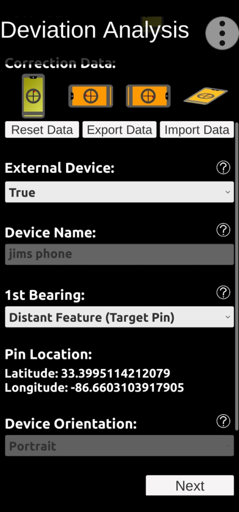
Deviation Analysis Setup Screen (note distant feature map coordinates)
Under “Correction Data” (image above), notice four phone orientation symbols – Portrait, Landscape (left), Landscape (right), and Horizontal. The Portrait symbol is green indicating that correction data has already been collected from a previous location – for the Portrait orientation; and that’s OK. When we collect fresh deviation data from the current site for the Portrait orientation, the older data will be replaced. The orange color of the remaining symbols indicates that NO correction data exists, at all.
Since we will be collecting deviation data for the Vectronix rangefinder (Portrait orientation – default), “External” device should be indicated as – “True“.
The smartphone device we are using is “Jim’s Phone” – Samsung 23S MAX.
We will be taking the first (reference) bearing on the identified distant feature – as noted in the “1st Bearing” setting. There are other options available to take the first reference bearing based on the sun’s positions – either a) looking towards the sun aligning with the shadow of a vertical object or b) looking away from the sun to align with the shadow.
Note that the distant object’s map coordinates are provided (for reference) in the setup screen.
The device orientation will be “Portrait” – the default orientation for the rangefinder.
After all the necessary parameters have been selected, the user will scroll to the bottom of the Deviation Analysis setup screen and click on the “Next” button to start the deviation data collection process. Collect the first deviation data reference point (targeting the water tower – using the smartphone / AugView Compass) by touching the active screen. An initial reference bearing of 53.7 degrees is supplied by the AugView Compass “corrected” azimuth reading; and the first data column is filled out (automatically) to show the correct (reference) bearings for data collection.
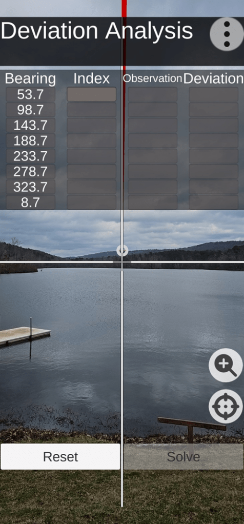
Reference Deviation Bearing Established (deviation data collection)
Referring to the next image, the Vectronix rangefinder is mounted on a tripod (equipped with an azimuth index ring) to facilitate accurate deviation data collection – in accurate 45 degree azimuth rotation increments. The azimuth ring is indexed to zero (0) for the first deviation error reading from the rangefinder – sighted in on the water tower.

Vectronix PLRF25C Rangefinder & Tripod
Note: The Vectronix deviation data collection process can be performed using the handheld mode – with the user depending on the AugView Compass augmented targets for pointing directions; but the handheld method is not as accurate as using the tripod. For this demonstration, a keypad (button) is being used to trigger the rangefinder so as not to introduce any disturbance (movement) when an azimuth reading is being taken.
The user manually enters a “zero” index value into the Deviation Analysis screen; and the AugView Compass app will increment that zero index value by 45 degrees – in anticipation of receiving additional manual data entries corresponding to the rangefinder deviation azimuth readings. The AugView Compass / Deviation Analysis screen is now ready to receive (manually) the rangefinder deviation azimuth readings – 8 readings.
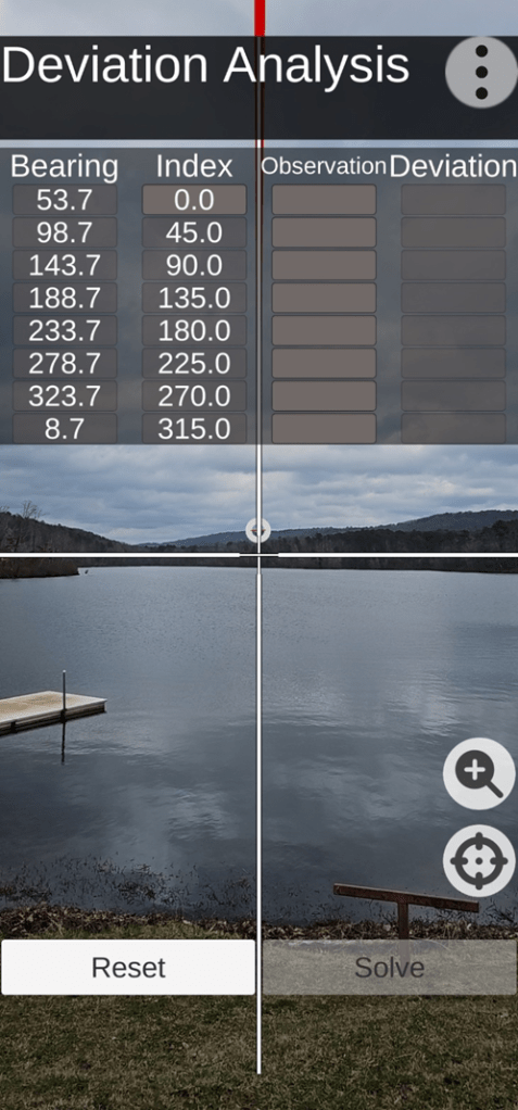
Indexed Deviation Analysis Screen
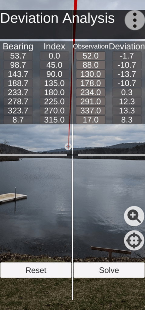
Completed (populated) Deviation Analysis Screen
After the Deviation Analysis screen has been populated (manually), the user clicks on the “Solve” button – thus activating AugView Compass app to compute the deviation correction parameters applicable to the Vectronix rangefinder. The setup and deviation data collection process usually takes about 3 to 5 minutes – after the distant target has been identified.
Narrative: Rangefinder Deviation (azimuth error) Analysis Review
NOTICE: The following data analysis (data tables & charts) is presented to illustrate the data processing work performed inside the AugView Compass app. There is no need for the user to be burdened with this work. The work is presented here for the reader’s benefit (to understand what is going on behind the scenes).
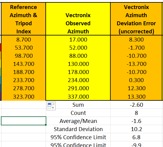
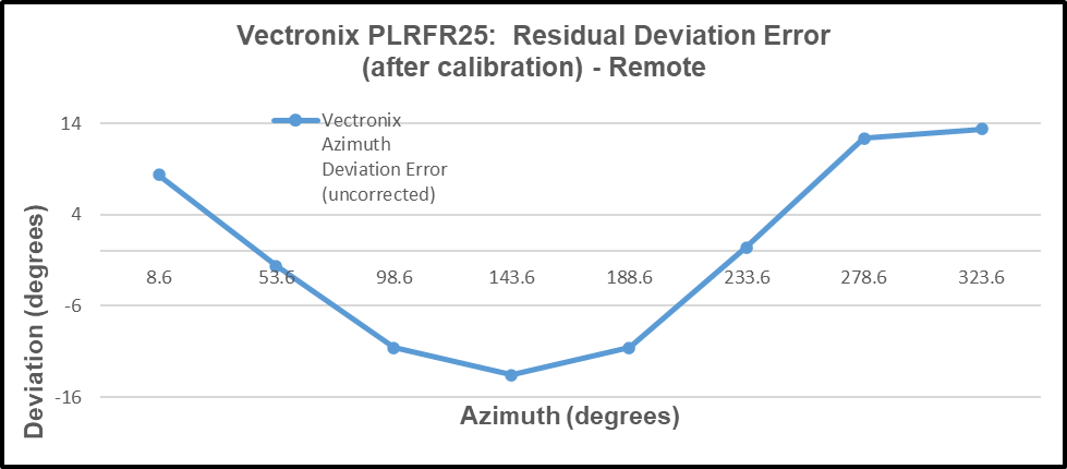
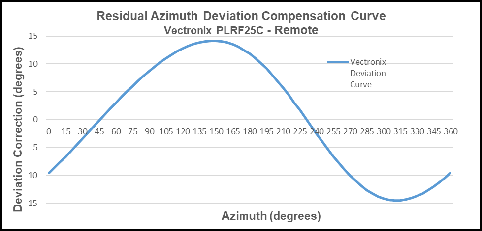
The rangefinder azimuth deviation errors ranged from a minimum value of (-13.7) to a maximum value of (+13.3) throughout the entire 360 degrees of measurement. This table is sorted (smallest to largest) based on the reference azimuth data column.
The AugView Compass solution for the deviation compensation parameters produced the following results.
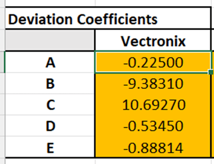
Using the deviation coefficients (above), the azimuth error correction calculations produced the following results (next image) – a maximum remaining error of (+2.5) degrees and a minimum remaining error of (-3.75) degrees throughout the entire 360 degrees of measurement.
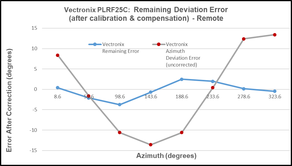
Thus, the user has a useful deviation curve available for future applications of the rangefinder.
The deviation curve (above) is presented (below) in the form of a polar plot to emphasize the 360-degree range of its application.
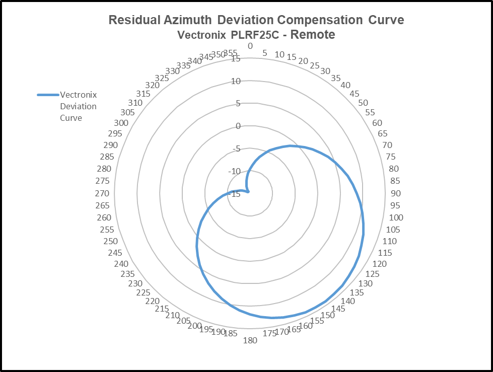
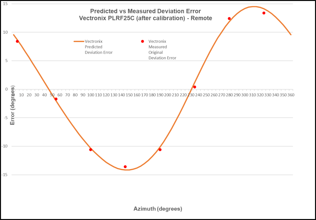
The “negative” of the deviation curve is the “predictor” curve for the rangefinder. Comparing the predictor curve with the original deviation data collected from the rangefinder gives us a strong indication of how well this deviation curve will work to correct rangefinder azimuth errors throughout the entire 360-degree range of measurement.
AugView Compass app is capable of analyzing the compass azimuth deviation error of any third-party a) smartphone compass app, b) rangefinder / binocular with compass, or c) electronic compass unit. The manufacturers of such apps, rangefinders, or electronic compass units are capable of using the deviation coefficients provided by AugView Compass to correct their own deviation azimuth errors – it’s a very fast and easy implementation.
PUNCHLINE:
It’s interesting to note that one way to enhance/improve the probability of achieving a first round strike/hit of a mortar or artillery round in the field is to correct (fix) the forward observer’s rangefinder (currently erroneous) azimuth readings using a smartphone with the AugView Compass app. That’s a $12 (4 minute) fix for a $10,000 rangefinder; and every soldier in the field (with a smartphone) could become an “instant” forward observer.
For instance: (assume accurate range and inclination angle readings)
- If the water tower were to become the intended mortar target, the rangefinder azimuth error is 1.86 degrees – resulting in a mortar round impact error of 446 feet left of the water tower. This is a fortunate example; because, at this particular azimuth, the error is small.
- If some other remote target were to be selected to receive mortar fire (with a maximum demonstrated azimuth error of 14+ degrees), the mortar round would miss the intended target by 3,475 feet. There’s no need for this scenario to play out when AugView Compass is available to correct the rangefinder compass readings such that a nearly zero error is achieved – throughout the entire 360 degree range of measurement.
User Value Proposition (Conclusions)
Conclusion: The manufacturer’s recommended calibration procedures should be followed.
Conclusion: The AugView Compass app a) augments the manufacturer’s recommended calibration procedures and b) compensates residual (after calibration) compass azimuth deviation errors caused by local environmental magnetic/electromagnetic influences.
Conclusion: The AugView Compass azimuth error correction results are “device dependent”.
Conclusion: The “experts” who publish reviews of smartphone compass apps need to extend their “analysis” methods to include an evaluation/determination of the compass app’s accuracy (or lack thereof).
Conclusion: Smartphone compass users [customers] can a) use the AugView Compass smartphone app to collect residual azimuth deviation [error] data from any electronic compass employed in a wide variety of real-world operating conditions – in a faster, better (easier), and cheaper way – and b) receive the AugView Compass azimuth error compensation coefficients [correction parameters] immediately – to be shared with the compass app’s vendor [or the user’s own software] to compensate the azimuth errors being encountered locally.

Leave a comment