
Case Study 1-B: Vectronix PLRF25C Laser Rangefinder (with compass) in Minimal Electromagnetic Field – Picayune, MS (test site)

Purpose: This blog is created to help readers a) better understand electronic compass [smartphone or rangefinder] residual azimuth deviation errors b) quantify the errors, c) model the errors, d) compensate for [correct] the errors, and e) influence their app vendor to apply the correction method within the affected smartphone app. Basically, we need to know (accurately) whether to go up / down the stream (path) we are traveling on.
Background:
This post will present the test results of the Vectronix PLRF25C (with compass) operated at the Picayune, MS test site with a minimal magnetic/electromagnetic field. Recall that the previous post in this series presented the test results of the Vectronix PLRF25C (with compass) operating in the Birmingham, AL test site with a strong magnetic/electromagnetic field.

The Picayune, MS test site exists in a 20 acre cow pasture with minimal magnetic/electromagnetic influence (field). The cattle were curious (disruptive) about what was taking place in their pasture. Recall that the Picayune, MS test site is 264 miles southwest of the Birmingham, AL test site. The major issues at the forefront of this test include:
- What is the impact (if any) of changing location (latitude change) on the effectiveness of the method for correcting residual compass (azimuth) deviation errors – for the Vectronix PLRF25C rangefinder (with compass)? Fact: The earth’s magnetic field strength changes with the geographic location of the observer.
- What is the impact (if any) of changing the operating environment (minimal magnetic/electromagnetic influence) on the effectiveness of the method for correcting residual compass (azimuth) deviation errors – for the Vectronix PLRF25C rangefinder (with compass)? Fact: Electronic compass results (azimuth readings) are impacted by environmental influences.
- What is the impact (if any) of not recalibrating the rangefinder compass on the effectiveness of the method for correcting residual compass (azimuth) deviation errors – for the Vectronix PLRF25C rangefinder (with compass)? Fact: The author was entirely willing to accept any error that may result from the decision not to recalibrate the device being tested – relying on the capabilities of the compensation method to correct the potential azimuth errors.
The Test Results
The data collection equipment and procedures used at test site B (Picayune, MS) were identical to those used at test site A (Birmingham, AL).
Recall: The residual compass deviation error persists throughout the entire 360 degree range of measurement. The following data table presents the collected azimuth data collected (yellow) and the associated azimuth deviation error (orange).
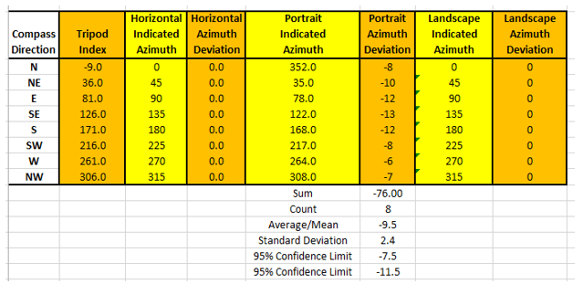
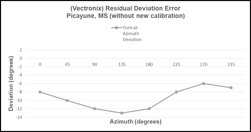
Notice that the Vectronix rangefinder is only operated in the “Portrait” orientation – normal operation. Therefore, no measured data is available for the “Horizontal” or the “Landscape” orientations – azimuth values are set to zero. The following chart depicts the “Residual Deviation Error” (Portrait Azimuth Deviation) of the Vectronix rangefinder compass.
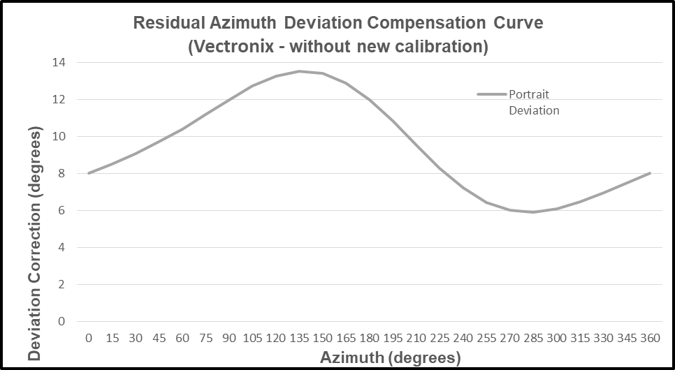
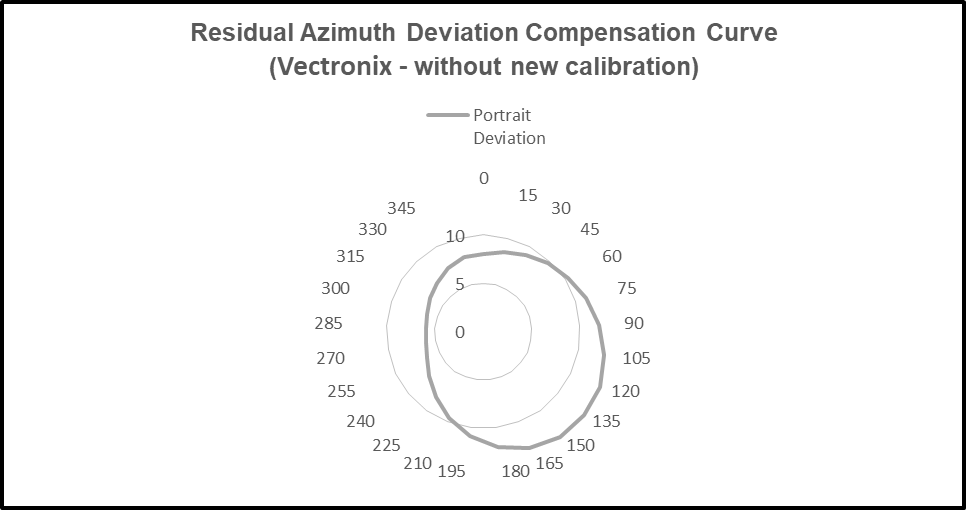
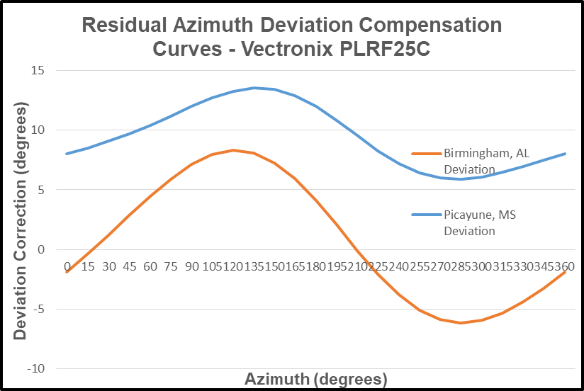
The “modeled” deviation curve (derived from the residual deviation error) for the Vectronix rangefinder is presented below. The modeled residual azimuth deviation compensation curve is presented in two different formats to allow the reader to seriously consider the deviation error – as measured throughout the full 360 degree range of measurement.
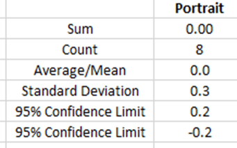
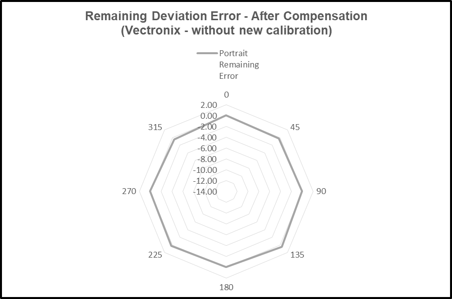
The compensated deviation errors (remaining azimuth errors after compensation) for the Vectronix rangefinder are depicted below. Again, two display formats are provided to strengthen the perceived impact of the compensation method.
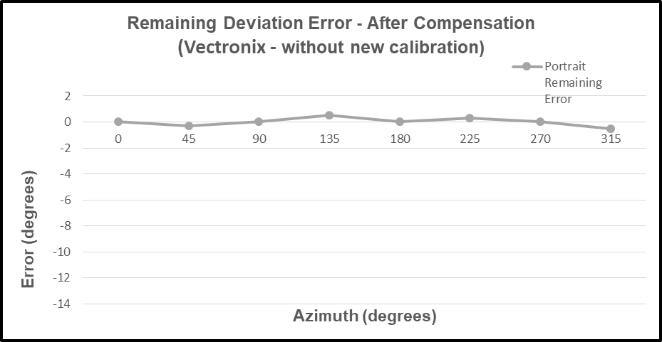
The predicted deviation errors for the Vectronix rangefinder are depicted in the following chart. The predicted error curve is the negative of the deviation curve; and the compensation method proved quite effective.

Now, we can assess the impact of the three issues identified in the “Background” portion of this post.
- What is the impact (if any) of changing location (latitude change) on the effectiveness of the method for correcting residual compass (azimuth) deviation errors. Response: Minimal
- What is the impact (if any) of changing the operating environment (minimal magnetic/electromagnetic influence) on the effectiveness of the method for correcting residual compass (azimuth) deviation errors. Response: Minimal
- What is the impact (if any) of not recalibrating the rangefinder compass on the effectiveness of the method for correcting residual compass (azimuth) deviation errors. Response: Minimal
We can see the impact (or lack thereof) of the three issues if we compare (graphically) the results from the Birmingham, AL test with the results from the Picayune, MS test. Recall that the residual azimuth deviation compensation curves were constructed from the deviation error model. The deviation compensation curves were used to compensate for the measured deviation error.
- Chart the shape (form) and magnitude of the residual deviation curves.
- Deviation (error) compensation is provided throughout the entire 360 degree range of measurements.
- One compass calibration was performed at the Birmingham, AL site; and compass calibration was avoided at the Picayune, MS site.
- A larger error magnitude – was exhibited in the data collected at the Picayune, MS site.
- A smaller error magnitude – as exhibited in the data collected at the Birmingham, AL site.
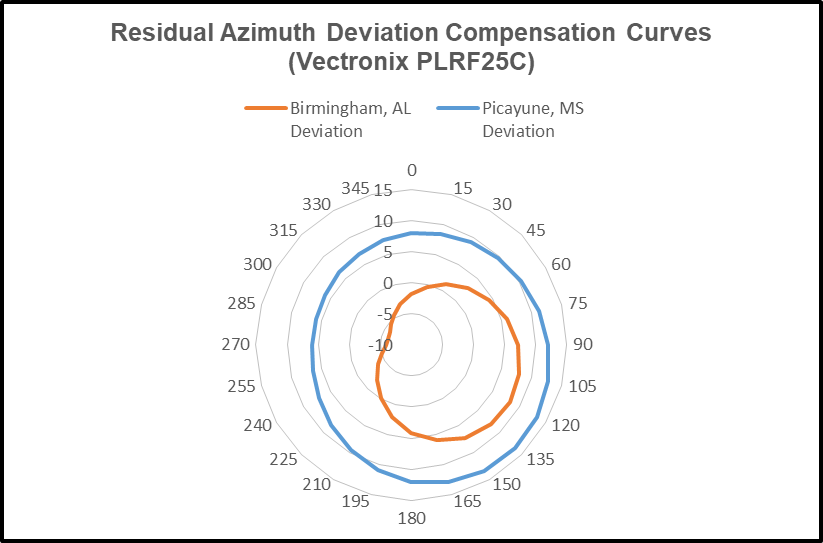
Recall that the measured residual deviation (azimuth) errors were (quite adequately) compensated in each test.
In the upcoming blog posts, we will deal with the iPhone (with compass) and several “compass” apps. As with the tests of the Vectronix rangefinder, the same methods will be used to collect, analyze, and present the results.
The reader can recall that these blog posts represent a series of posts dealing with the subject of “Fixing Rangefinder & Smartphone Residual Compass (azimuth) Deviation Errors”. All the subsequent posts in this series will (are planned to) follow a similar format. To date, three posts have been published:
- Fixing Rangefinder & Smartphone Residual Compass (azimuth) Deviation Errors
- Case Study 1-A: Vectronix PLRF25C Laser Rangefinder (with compass) in Strong Electromagnetic Field – Birmingham, AL (test site)
- Case Study 1-B: Vectronix PLRF25C Laser Rangefinder (with compass) in Minimal Electromagnetic Field – Picayune, MS (test site)

Leave a comment