
Row, row, row your boat gently up / down the stream???
Purpose: This blog is created to help readers a) better understand electronic compass [smartphone or rangefinder] residual azimuth deviation errors b) quantify the errors, c) model the errors, d) compensate for [correct] the errors, and e) influence their app vendor to apply the correction method within the affected smartphone app. Basically, we need to know (accurately) whether to go up / down the stream (path) we are traveling on – safely.
Background:
This post will present test results of the Vectronix PLRF25C rangefinder (with compass) operated at the Birmingham, AL test site with a substantial magnetic/electromagnetic field influence. This post will resolve the issue: “What can you do if the sun is not shining?“
The Birmingham, AL test site is set in an urban environment with strong magnetic/electromagnetic influences including:
- An electric power distribution station for eight (8) townhomes
- At least eight operating heating/cooling (heat pump) units of 3 to 4 ton capacity – aligned North/South within 50 feet of the test site (East side)
- An active highway – aligned North/South within 150 feet of the test site (West side)
Cloudy Day Deviation Curves
Problem Statement: How can compass residual deviation error compensation curves be established on a cloudy day – without the help of a distinct shadow to determine the sun’s azimuth and hence the True North direction?
Objectives:
- Use a “GPS-method” to determine True North on a cloudy day.
- Determine the True North direction using two GPS point locations.
- Collect compass residual deviation error data for each of the eight (8) cardinal compass directions using a rangefinder (with compass) – Vectronix PLRF25C.
- Determine the compass deviation (compensation) curves.
- Use the compass deviation curves to compensate for the measured azimuth errors.
- Use the “solar-method” to determine True North on a bright, sunny day.
- Determine the True North direction using the sun’s position – the solar method.
- Collect compass residual deviation error data for each of the eight (8) cardinal compass directions using a rangefinder (with compass) – Vectronix PLRF25C.
- Determine the compass deviation (compensation) curves.
- Use the compass deviation curves to compensate for the measured azimuth errors.
- Compare the “GPS-determined” (cloudy day) compass deviation curves to the (sunny day) compass deviation curves determined using the solar (sun position) method.
In prior blog posts the sun position was used [exclusively] to a) determine the True North direction and b) establish the eight [8] primary compass points necessary for collecting compass azimuth residual deviation error data. The sun position was used since sun position is irrefutable. There is no real (alternative) compass that could be used; because real compasses (magnetic or electronic) are always in error – to some unknown degree.
The natural question that arises is: “How can True North be established on a cloudy day?” In this blog post the author will answer this question using readily available commercial grade GPS technology. As well, the author will make a direct comparison of the results obtained using GPS technology to the results obtained using the sun position. The comparisons and results made available in this blog post will not be aimed at securing a “land survey” grade accuracy but rather a “just-good-enough” accuracy level. There’s no need wasting time, money, effort, and patience when just-good-enough will do the job at hand. Most user’s applications are not land survey grade applications; and most are not military grade applications.
Objectives 1a & 2a: Determine the True North direction
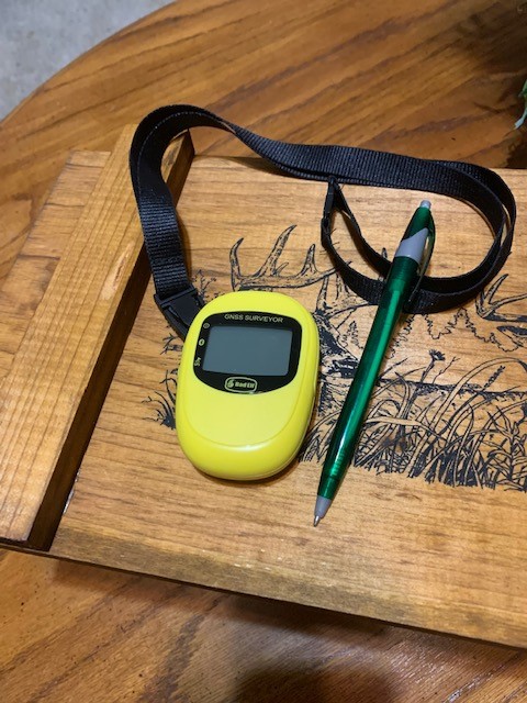
First, using a good quality (reasonably priced) handheld external GPS unit (Bad Elf/Surveyor) linked to the iPhone via (low power) Bluetooth, establish two (2) geographic locations (points) having (generally) a North-South orientation – to “simulate” a good, morning sun azimuth. In other words: “Take your best shot; and if you have a handheld magnetic compass, use it.”
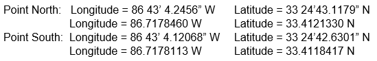
The following Google Earth image depicts the Birmingham, AL test site – which experiences a strong electromagnetic influence. The Bad Elf GPS unit was placed to have a good stationary “sky” view – first, to locate the Point South and second, to locate the Point North. For each point, three GPS readings were taken. One reading was taken immediately after the Bad Elf unit was placed in its stationary position; another reading was taken 15 minutes later; and a final reading was taken after 30 minutes in the same position. Each GPS location is depicted in the following Google Earth image. The final reading (after 30 minutes) was used to make the “simulated solar” azimuth determination. Notice how the GPS position wanders into its final location – as time passes.

Using Google Earth, the azimuth of the line between Point North and Point South was determined to be 168.94 degrees; and the distance between Point North and Point South was determined to be 49.33 feet.
Consider using another approach to determine the azimuth and distance.
Reference: Use the following mathematics from “Azimuth Calculator”, establish the True North direction – the second method.
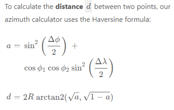
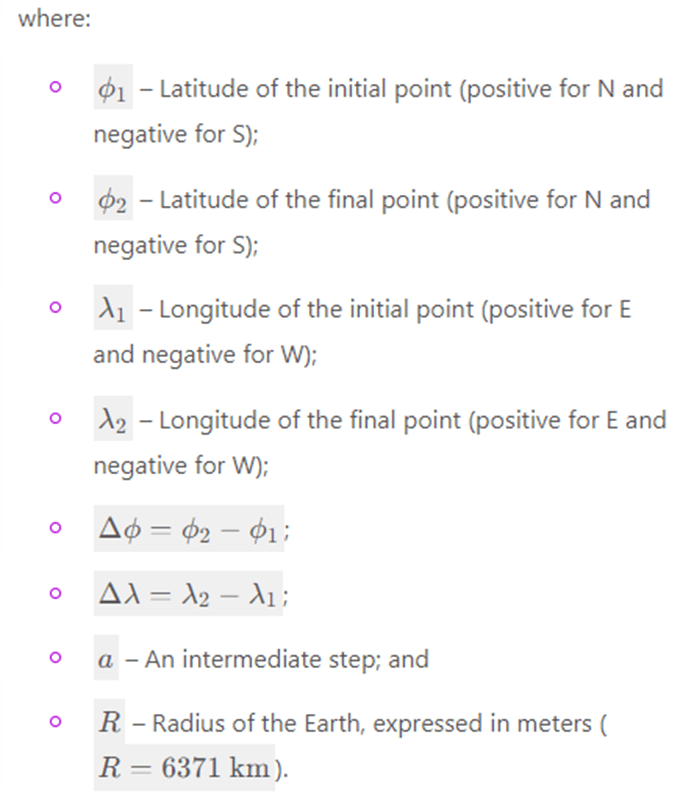
Input latitudes and longitudes in the decimal degrees notation. The resulting distance will be expressed in meters.
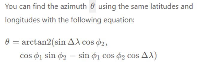
The resulting azimuth value will be expressed in radians and converted to degrees.
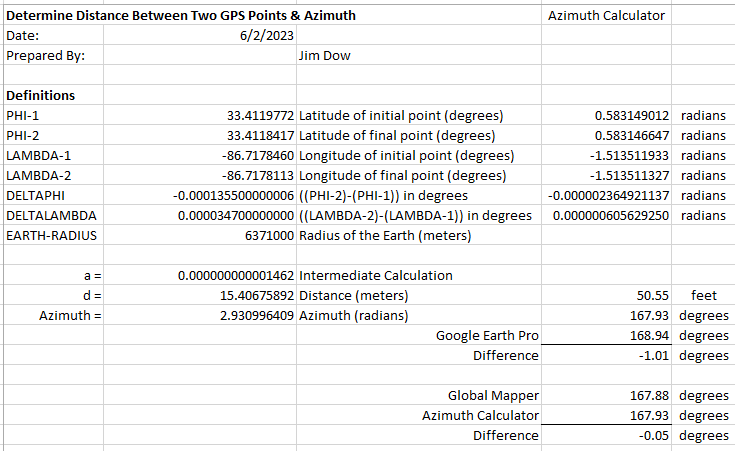
Note that the azimuth value determined by the Azimuth Calculator is 167.93 degrees; while the azimuth value provided by Google Earth Pro is 168.94 degrees. This difference of (-1.01 degrees) is acceptable. But, let’s see what Global Mapper has to say – a third approach. Global Mapper says that the North-South azimuth equals 167.88 degrees. This difference of (-0.05 degrees) is acceptable also. Based on the general agreement between Azimuth Calculator, Google Earth, and Global Mapper, the author chooses the Global Mapper result – a matter of personal preference – as illustrated below.

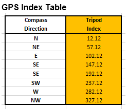
With the tripod azimuth index set at 180 and aligned with the N-S vector (Point-North to Point-South) pointing toward Point-South, the tripod head is rotated counter-clockwise 167.88 degrees to find True North – resulting in an apparent azimuth of +12.12 degrees (clockwise), measuring from the tripod location (along the line between the Point-North/Point-South vector and pointing toward the Point-North). This is the result of using the GPS method to approximate the True North direction.

In order to compare the “GPS-determined” (cloudy day) compass deviation curves to the (sunny day) compass deviation curves determined using the solar (sun positon) method, the sun’s azimuth was determined to be 174.4 degrees – using the solar method described in prior posts. Based on a 180 tripod index, the solar True North direction is +5.6 degrees (clockwise) off our North – South vector, from the tripod location.

The reader can refer to the first blog post “True North” to see how the solar method of determining True North direction is used – in detail.
Objectives 1b & 2b: Collect compass residual deviation error data.
The (GPS) True North direction has been established to be +12.12 degrees (clockwise) from the (GPS) North-South vector, as measured from the tripod location (along the North-South line, point toward the Point-North location). Therefore, a set of index values (table) can be prepared to ensure that all eight (8) azimuth measurements are collected using the tripod index ring. It is not desirable to use ad hoc sighting techniques to collect azimuth deviation (error) data when the use of such techniques will only introduce more error.
Recall, the (solar) True North direction has been established to be +5.6 degrees (clockwise) from the (GPS) North-South vector, as measured from the tripod location (along the North-South line, point toward the Point-North location). Therefore, a second set of index values (table) was prepared to ensure that all eight (8) azimuth measurements are collected using the tripod index ring. The solar index table is presented below.

The Vectronix PLRF25C rangefinder was used to collect all the compass residual deviation (azimuth) error. For this case study, the author (again) chose NOT to recalibrate the compass of the Vectronix rangefinder since it was originally calibrated on this test site. The compass azimuth deviation error compensation method was challenged to “do its job”.
Recall, from a prior blog post which tested the Vectronix rangefinder at both test site A (Birmingham, AL) and test site B (Picayune, MS), the Vectronix rangefinder compass was recalibrated prior to performing the first test at the Birmingham, AL site; and the compass was NOT recalibrated for the test at the Picayune, MS test site. Since this test is being performed back at the Birmingham, AL test site, there is no need to recalibrate the rangefinder compass.
Recall: The residual compass deviation error persists throughout the entire 360 degree range of measurement. The following data table presents the collected azimuth data (yellow) and the associated azimuth deviation error (orange).
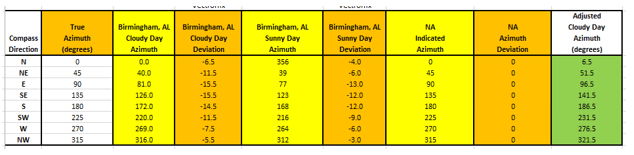
Notice that the Vectronix rangefinder is only operated in the “Portrait” orientation – normal operation. Therefore, no measured data is available for the “Horizontal” or the “Landscape” orientations – NA (not applicable) azimuth values are set to zero. The collected azimuth deviation (error) data are presented in the following charts.

The residual azimuth deviation error curves have been presented in two different formats to allow the reader to seriously consider the deviation error – as measured throughout the full 360 degree range of measurement.
Objectives 1c & 2c: Determine the compass deviation curves.
From the azimuth deviation error data collected (Objective 1b and Objective 2b), deviation curves can be prepared. The collected error data were modeled; and the new (sunny/cloudy) deviation compensation curves were constructed.
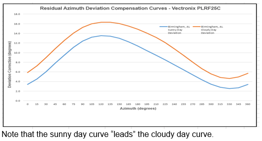
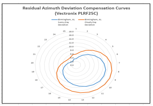
Again, the residual azimuth deviation compensation curves have been presented in two different formats to allow the reader to seriously consider the deviation error – as measured throughout the full 360 degree range of measurement.
Objectives 1d & 2d: Use the compass deviation curves to compensate for the measured azimuth errors.
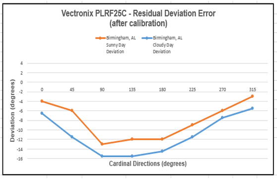
The compensated deviation errors (remaining azimuth errors after compensation) for the Vectronix rangefinder are depicted below. Again, two display formats are provided to strengthen the perceived impact of the compensation method.
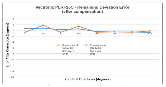
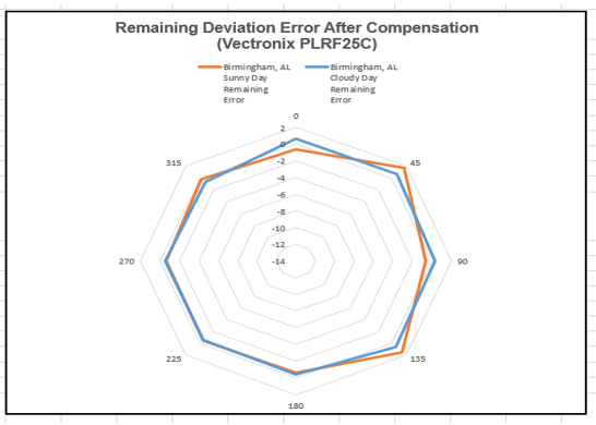
We can see from the two charts depicted above that the error compensation model is working quite well.
Objective 3: Compare the GPS & Solar-determined compass deviation curves.
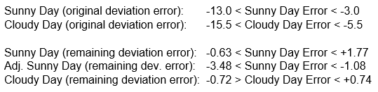
Compare the deviation compensation curves from Objectives 1d & 2d by taking the difference between the GPS-determined deviation values and the solar-determined deviation values – all along the curves.
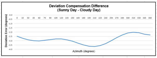
The average cloudy day deviation compensation value is -2.9 degrees. If this average cloudy day deviation compensation value is added back to the sunny day deviation compensation value, the original sunny day remaining deviation error is impacted (adjusted) as shown in the following chart. Even if the cloudy day compensation data is applied to the sunny day azimuth deviation data, the results are “not-that-bad”.
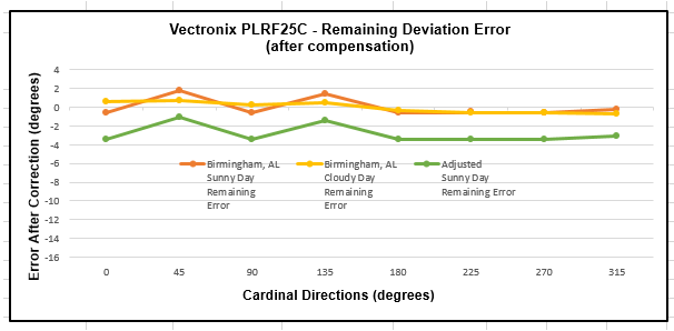
From the chart above, even the “adjusted” remaining sunny day deviation error is significantly less than the original error values. The sunny day ‘adjusted’ deviation values are determined by applying the cloudy day compensation values to the original sunny day deviation error values.
Conclusions:
- For a lot of applications, the GPS (cloudy day) method of determining the True North direction (approximation) is adequate for collection of azimuth deviation (error) data – a necessary and sufficient prerequisite for the production of residual azimuth deviation compensation curve(s).
- The “Azimuth Calculator” mathematics (implemented in Microsoft/EXCEL) proved to be a good method for determining the azimuth between two GPS point locations – which provided the basis for determining the True North direction (approximation).
- The Bad Elf/Surveyor handheld GPS unit proved to be adequate for determining GPS point locations – from which the True North direction (approximation) could be determined.
- The “good comparison” of the two sets of deviation compensation curves shown above (GPS-method vs Solar-method) bodes well for the repeatability and adequacy of the Vectronix rangefinder azimuth measurements – obviously, not too many operator errors were introduced into the data collection process.
- The electronic compass azimuth deviation (error) compensation method worked well (as expected) throughout this case study.
What’s coming?
In future blog posts, the author hopes to continue to evaluate additional rangefinders and smartphone (iPhone) compass apps as candidates for implementation of this electronic compass azimuth deviation (error) compensation method. Recall, users will be capable [soon] of easily and quickly a) evaluating any electronic compass, any rangefinder [with compass], and any smartphone compass app to b) determine the residual compass azimuth deviation error compensation curves and c) upload those compensation curves to any device/app that has been adapted [by the vendor] to take advantage of this azimuth error compensation method. This is what we’ve all been waiting for – the ability to “fix” residual compass azimuth deviation errors.

Leave a reply to Fixing Rangefinder & Smartphone Residual Compass (azimuth) Deviation Errors – List of Posts – Tru-Path Cancel reply