
Row, row, row your boat gently up / down the stream???
Purpose (RECALL): This blog post is created to help readers a) better understand electronic compass [smartphone or rangefinder] residual azimuth deviation errors b) quantify the errors, c) model the errors, d) compensate [correct] the errors, and e) influence the app vendors to apply the correction method within the affected smartphone app. Basically, we need to know (accurately) whether to go up / down the stream (path) we are traveling on.
Goal: The goal of this blog post is demonstrate the repeatability of the TruPath Compass app when a) collecting residual (after calibration) compass azimuth deviation (error) data, b) modeling the deviation data to produce deviation compensation curve(s), and c) applying the deviation compensation curve(s) to produce corrected (compensated) smartphone compass azimuth readings.
Justification: Over the past several years, hundreds and thousands of smartphone users have complained (via internet users’ forums) about their inability to use the compass apps – and rightly so. “Experts” have offered many “fixes” to resolve the issue; yet smartphone compass apps (all) have remained notoriously inaccurate. TruPath Compass app fixes the issues!
Hypothesis: After recognizing a problem (smartphone compass error), if the error can be predicted; the error can be corrected.
Problem Statement: How can smartphone compass azimuth error be predicted (quantified / modeled) and then be compensated (corrected) in real world situations?
Solution Characteristics: In order for smartphone compass azimuth error to be compensated (corrected), the following statements should be true.
- The error must be quantified – throughout the entire 360 degree range of measurement – in a manner that adds minimum cost to the user in terms of a) out-of-pocket expense, b) time and effort, and c) investment in education and/or training. This means that descriptive data must be collected to quantify the error.
- Manufacturer’s recommended compass calibration procedures must be factored in (and applied) to account for the “hard iron” and “soft iron” effects attributed by the materials and component(s) arrangements within the smartphone itself. The smartphone compass azimuth error to be compensated is the residual (after calibration) error resulting from environmental magnetic/electromagnetic influences – external to the smartphone itself.
- The deviation data collected about the compass azimuth error must be “modeled” in such a way that the predicted error can be “added back” (subtracted) from the original erroneous azimuth readings to compensate (correct) the error(s) – in a repeatable and reliable manner over the entire 360 degree range of measurement – within the local environment – over a wide (Latitude) geographic area.
Solution: The TruPath Compass smartphone app exhibits all the positive solution characteristics stated above.
Background:
This post presents multiple sets of test results of the new Android / TruPath Compass app (prototype) operated at a single test site. Each test was performed using a separate and unique setup operation. The results of these tests demonstrate the repeatability and reliability of the TruPath Compass app to compensate (correct) residual compass azimuth error for any electronic compass (smartphone, laser rangefinders, electronic compass, etc.).
- The selected Birmingham, AL test site has a strong magnetic/ electromagnetic field influencing the earth’s magnetic field – and thus, the smartphone electronic compass.
- A small test range was prepared for accurately collecting three (3) separate (and independent) sets of residual compass azimuth deviation (error) data.
- The first (Test 1) and second (Test 2) sets of deviation data were collected using TruPath Compass’ ability to support the use of a camera tripod (with indexed azimuth ring) – a mechanical indexing approach to eliminate the need for any type of sighting operations by the user.
- The third set of deviation data (Test 3) was collected using TruPath Compass’ augmented reality capabilities. A camera tripod was used to provide a more stable platform for data collection while sighting on a virtual target. TruPath Compass also supports handheld data collection – as may be desired.
- The data collected included:
- A reference azimuth (a known base direction) was established from which to incrementally advance to other (sequential) known offset azimuths (45 degree increments, throughout a full 360 degree range of measurement). Although the True North direction was used as the reference direction for these tests – for convenience of the reader, TruPath Compass does NOT require the use of True North as the reference azimuth (starting point) for azimuth data collection.
- Quantified azimuth error data (the difference between the known azimuth and the measured azimuth) was collected – a total of eight (8) measurements. Using TruPath Compass, the total time required to collect the azimuth error measurements was less than 4 minutes per test – typical.
The data collection equipment and procedures used for all three (3) tests were identical to those used at the original Birmingham, AL test site for several prior posts. Refer to the original post/page at http://www.tru-path.org.
- True North (reference direction) was established (staked out) based on the sun position (solar azimuth) relative to the test site’s observer (geographic) location on the date/time the tests were performed – a correct, defendable, and independent reference direction.
- The Android/TruPath Compass app was set to indicate azimuths relative to True North.
- The same observer location and True North target location were used during all three repeatability tests – to provide a consistent frame of reference.
- The Android phone (sensors) were re-calibrated prior to initiating the first test.
- Only the “portrait” phone orientation was used for the three repeatability tests.
- Recall: Residual (after calibration) compass deviation error persists; and the error magnitude varies throughout the entire 360 degree range of measurement.
Test Site Characteristics – Birmingham, AL
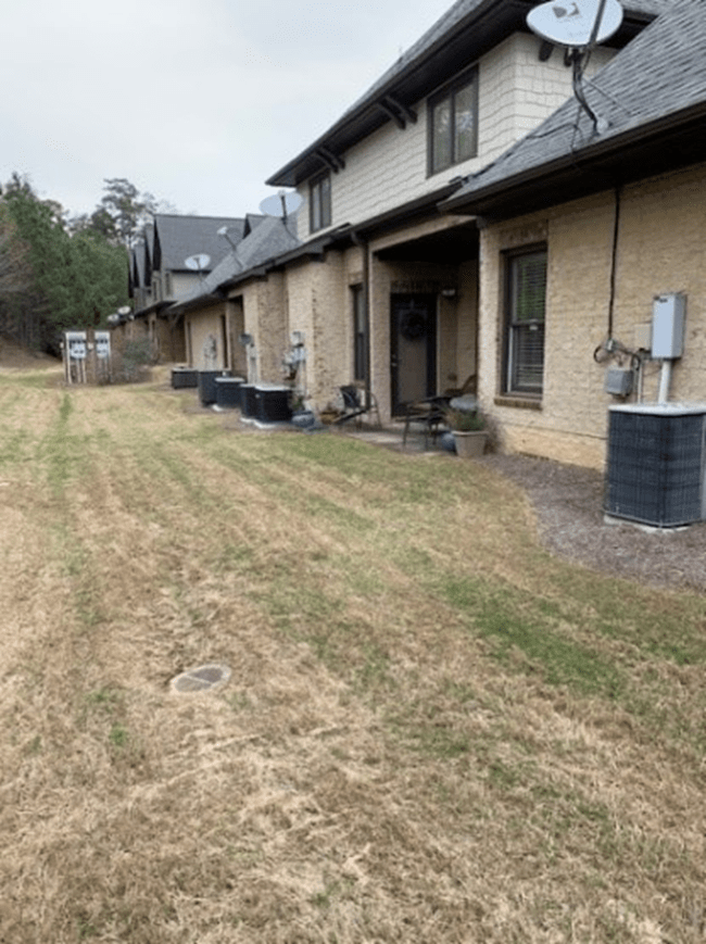
The Birmingham, AL test site is set in an urban environment with strong magnetic/electromagnetic influences including:
- An electric power distribution station is located adjacent to eight (8) townhomes.
- At least eight operating heating/cooling (heat pump) units of 3 to 4 ton capacity – aligned North/South are within 50 feet of the test site (East side).
- An active highway – aligned North/South is within 150 feet of the test site (West side).
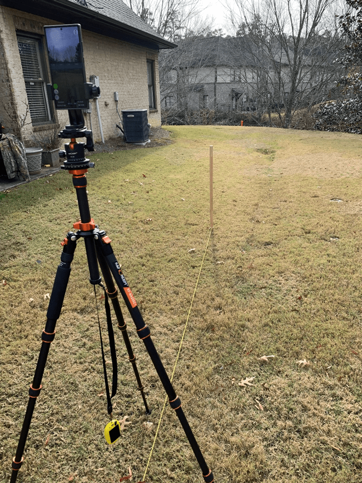
The observer’s location was staked out within sighting distance of a vertical (pole) target used to cast a good shadow (sun shadow). The shadow of the vertical stake was used to establish the azimuth of the sun – and thus, the azimuth (direction) to True North – as facilitated by the TruPath Compass app. Refer to the following image.
Observer Location (GPS)
- Latitude: 33.4118433
- Longitude: -86.7178023
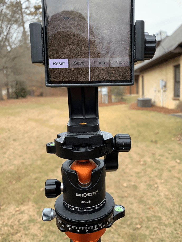
Smartphone in portrait orientation
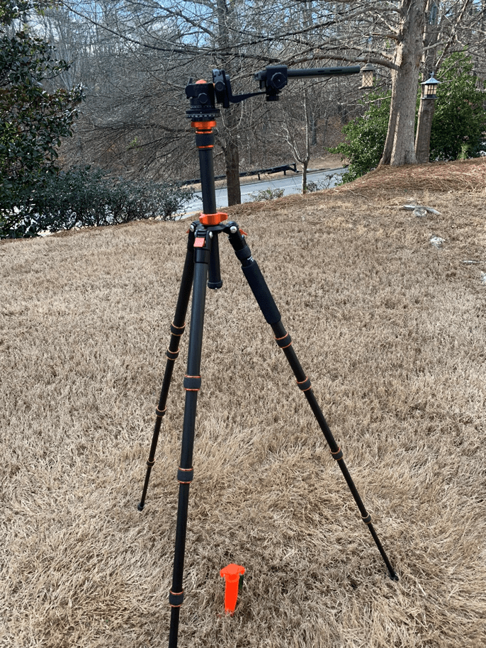
The tripod was capable of mounting a smartphone in either a portrait, landscape, or horizontal orientation. For these tests, only the portrait orientation was used – a) sufficient for demonstrating the repeatability of the deviation measurements and b) without overwhelming the reader with voluminous repetitive data.
Smartphone in horizontal orientation
The tripod featured an azimuth ring for mechanically (reliably) controlling the azimuth direction of the smartphone – no sighting error involved.
Camera Tripod with Azimuth Ring
From the observer’s location (tripod), a reference azimuth (True North) was established (staked out) using the sun’s position (solar azimuth) as a basis – as previously mentioned and demonstrated in previous blog posts.
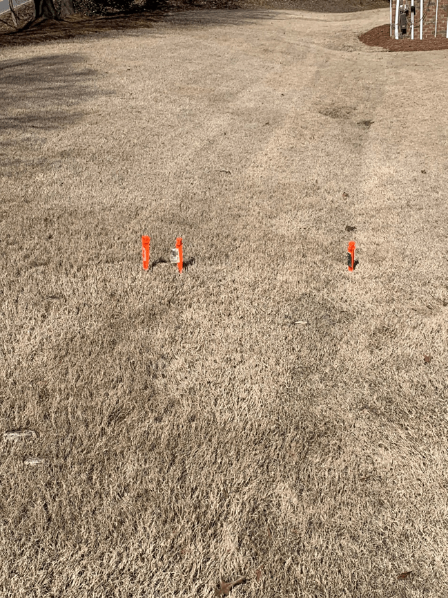
Distant Feature (target) Stakes
In the preceding image, the right-most stake (distant feature) indicates the True North azimuth from the observer’s location. The central-most stake indicates an azimuth of 355 degrees; while the left-most stake indicates an azimuth of 354 degrees as seen from the observer’s location. The central-most and left-most stakes were used (casually) to check azimuth readings using the TruPath Compass – the author’s choice to check compass calibration and error compensation.
Right-most Stake Location (GPS)
- Latitude: 33.4119360
- Longitude: -86.7177999
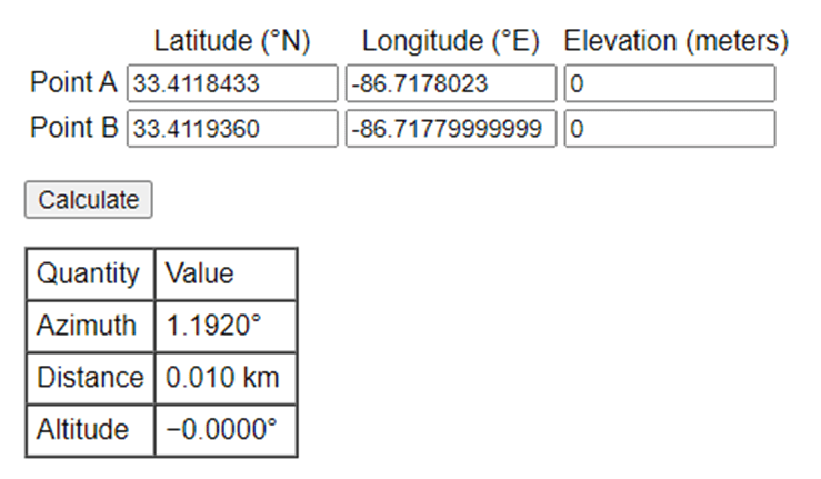
Notice that the Longitude of the observer location (Point A) and the Longitude of the distant feature point (Point B) are not identical. This difference is due to the inaccuracies of the commercial GPS receiver used during these tests. This difference (error) is not unusual for these types of tests “in the real world”; but this error is small and acceptable for this work.
Referring to the following table, the azimuth between the observation point (Point A) and the distant feature (target) point (Point B) was calculated to be 1.192 degrees – using a 64 bit computer and double precision math. When using the smartphone operating system with its inherent precision, the author might expect to experience somewhat less in terms of calculation accuracy.
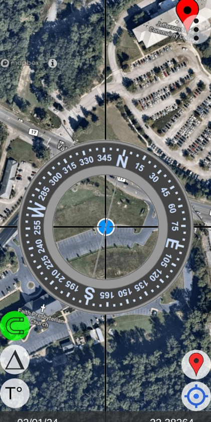
Moving along, the following image depicts the author’s first calibration/compensation check. Notice that TruPath Compass allowed the author to place (geo-locate) a marker on the map background corresponding to the location of the left-most (True North) target (stake). The marker can be placed on the map background using a Pan/Zoom capability; and that placement can be edited using either survey coordinates or GPS coordinates. The image indicates that the target is placed to give a reference True North azimuth from the observer’s location (the blue dot – a “current” GPS location).
- The “red” vertical bar directly below the “N” character (True North) label indicates that TruPath Compass’ compensation is “ON” – indicated, as well, by the green (upper case delta symbol) button along the lower left side of the screen. The width/thickness of the red bar indicates the magnitude of the error compensation. The algebraic sign of the compensation value is indicated (depending on which side of the vertical screen alignment line the red bar lies) – left side (negative)/right side (positive). The signed numeric value of the compensation angle is shown at the bottom of the image – indicated by the lower case delta symbol (-1.3 degrees).
- Note: The horizontal “horseshoe” button (lower left side of screen) is “green” indicating that the state of compass calibration is “good”.
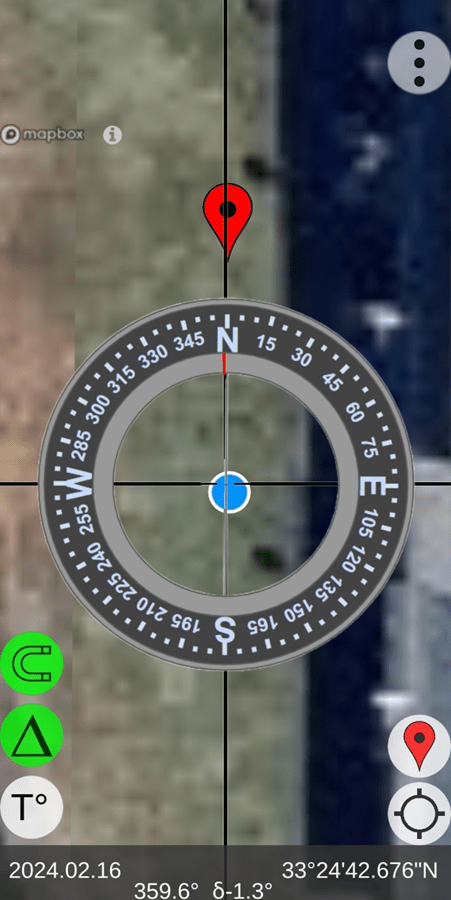
TruPath Compass “Home” Screen
The following image depicts the author’s second calibration/compensation check using the TruPath Compass’ virtual reality camera display (Live View – accessed via the Menu button shown in the upper-right corner of the screen. Again, the author can be satisfied that the compass calibration is operating well. Notice that in this image, the compensation is turned “OFF” – as indicated by a “white” compensation button and by a compensation magnitude of zero (0 degrees) at the bottom of the image.
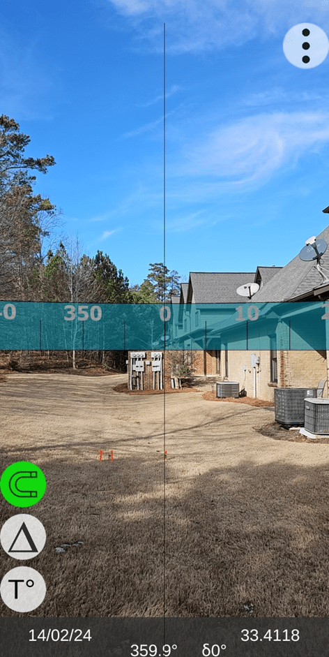
TruPath Compass “Live View” Screen
Test Results
Data Collection (Test 1): (time required to collect deviation data < 4 minutes)
(use of tripod azimuth ring – one target sighted / seven targets indexed)
All test results presented in this post are device specific: Android / Samsung S23 MAX.
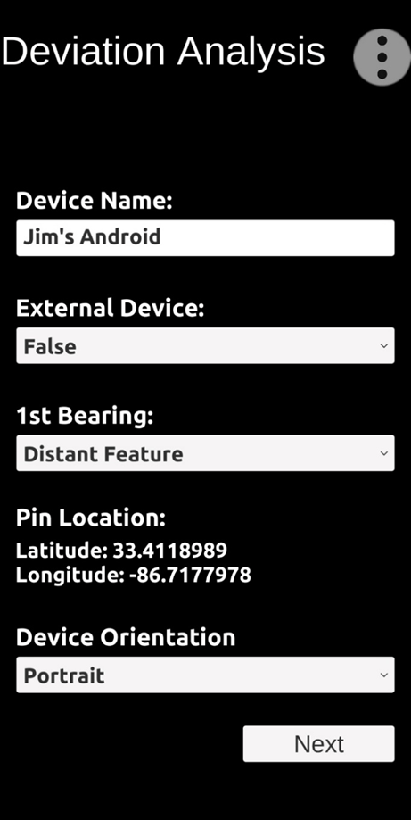
TruPath Compass provides a “setup” screen that allows the user to specify the circumstances under which the deviation data will be collected. Refer to the following image.

For Test 1,
- The True North target will be used as the “distant feature” to define the reference azimuth from which to a) incrementally swing the phone and b) collect the deviation (error) data points.
- Each successive target (azimuth) will be reached by rotating the phone incrementally by 45 degrees (clockwise) using the tripod index ring – as prompted by TruPath Compass. Except for sighting in on the reference (True North) stake, the user does not need to sight in on any target.
- Jim’s Android phone was mounted (on a tripod) in the Portrait orientation.
The following image depicts the first screen used to capture the first azimuth deviation (error) data point.
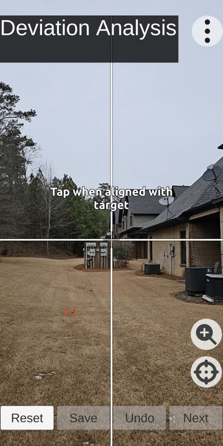
Situation: After sighting in on the right-most (True North) stake, the user will “Tap” near the center of the screen; and the first measured azimuth will be captured.
Simultaneously, TruPath Compass will bring up a second data capture screen indicating a) the bearing direction from the observation point to the True North target point, b) the magnitude of the first measured azimuth [Observation], c) the calculated azimuth deviation [error] value, and d) the direction of rotation to the “Next” Virtual Reality target point to be captured.
As depicted in the following image, two azimuth deviation points have already been collected.
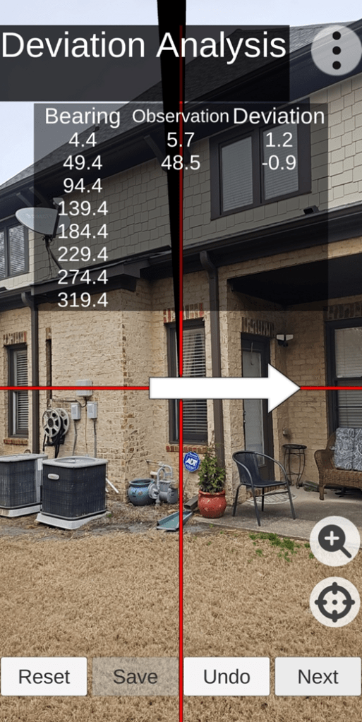
Situation: In the image above, the user has collected two data points; and TruPath Compass is indicating that the user should swing the phone in the direction of the arrow to the next (third) “indexed” target point. Restated: The user has clicked the “Next” button capturing the (second) azimuth data point, and TruPath Compass has activated the direction arrow.
Note: The color of the screen crosshairs can be changed (by the user – lower right button on screen) to provide background contrast, as needed. The available crosshair colors are white, black, red, green, and blue.
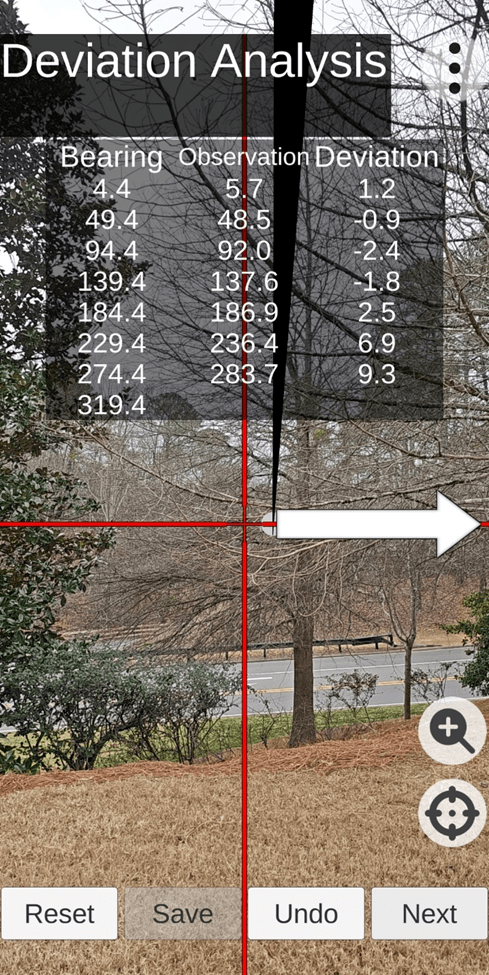
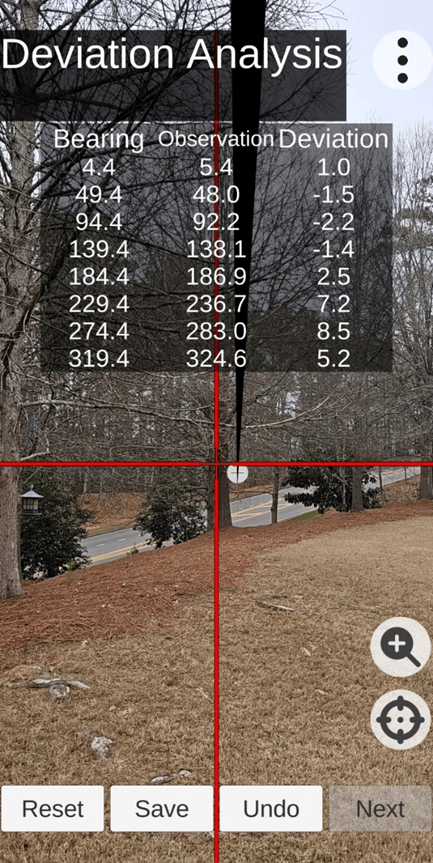
Situation: The preceding image indicates that the user has collected seven (7) of the required eight (8) azimuth data points. As the user clicks on the “Next” button, the eighth azimuth data point will be collected.
At this point, the user should click on the “Save” button to a) process the data collected, b) analyze the collected data – determining the compensation parameters for this case [phone orientation], and saving the results for future application. Now, the user can experience corrected azimuth readings using TruPath Compass.
Data Collection (Test 2): (time required to collect deviation data < 4 minutes)
(use of tripod azimuth ring – one target sighted / seven targets indexed)
Situation (special): The same smartphone, TruPath Compass app, range, tools, equipment, and procedures used in the first test were used to perform the second test as well. As such, the illustrations associated with Test 2 are abbreviated – for convenience of the reader.
Again, TruPath Compass provides a “setup” screen that allows the user to specify the circumstances under which the deviation data will be collected. Refer to the following image.
For Test 2,
- The True North target will be used as the “distant feature” to define the reference azimuth from which to incrementally swing the phone and collect the deviation (error) data points.
- Each successive target (azimuth) will be reached by rotating the phone incrementally by 45 degrees (clockwise) using the tripod index ring – as prompted by TruPath Compass The user does not need to sight in on a target.
- Jim’s Android phone was mounted (on a tripod) in the Portrait orientation.
The following image depicts the final deviation data capture screen used to capture the eight (8) deviation (azimuth error) data points.
Situation: In the image above, the reader can see that the user has collected all eight required (8) azimuth data points.
At this point, the user should click on the “Save” button to a) process the data collected, b) analyze the collected data – determining the compensation parameters for this case [phone orientation], and saving the results for future application. Now, the user can experience corrected azimuth readings using TruPath Compass.
Recall: The color of the screen crosshairs can be changed (by the user – lower right button on screen) to provide background contrast, as needed. The available crosshair colors are white, black, red, green, and blue.
Data Collection (Test 3): (time required to collect deviation data < 4 minutes)
(TruPath Compass – Augmented Reality – user sighting of all eight targets)
Again, TruPath Compass provides a “setup” screen that allows the user to specify the circumstances under which the deviation will be collected. Refer to the following image.

For Test 3,
- The True North target (stake) will be used as the “distant feature” to define the reference azimuth from which to incrementally swing the phone and collect the (necessary and sufficient) deviation (error) data points.
- Instead of using the tripod azimuth index ring to mechanically arrive at (occupy) each successive “known” target azimuth, the user sighted in on each individual Augmented Reality target successively – as prompted by TruPath Compass.
- Jim’s Android phone was mounted (on a tripod) in the Portrait orientation.
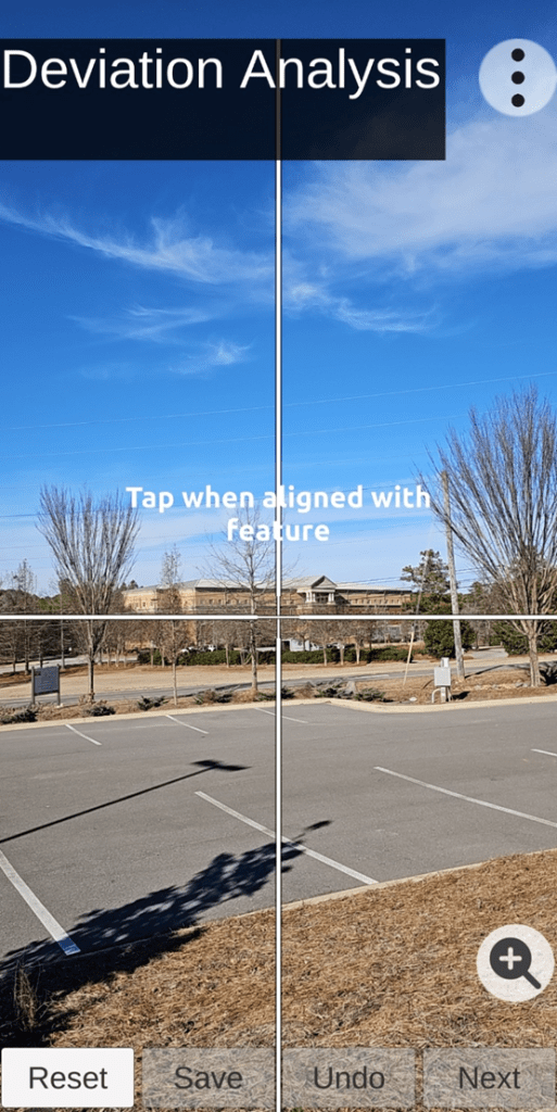
The following image depicts the first azimuth deviation data collection screen to be a) sighted on the True North stake and b) used to capture the first deviation (azimuth error) data point.
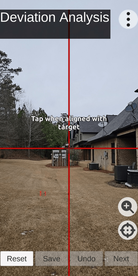
Situation: After sighting on the right-most (True North) stake, the user will “Tap” near the center of the screen; and the first measured azimuth will be captured.
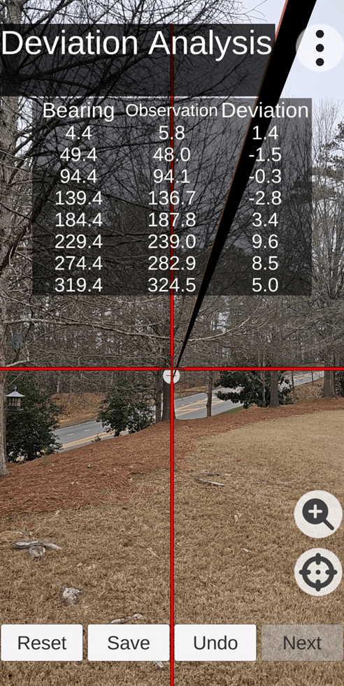
Simultaneously, TruPath Compass will bring up a second data capture screen indicating a) the Bearing direction from the observation point to the True North target point, b) the magnitude of the first measured azimuth [Observation], c) the calculated azimuth Deviation [error] value, and d) the direction of rotation to the “Next” Augmented Reality target point to be captured.
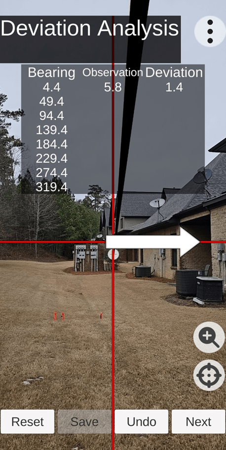
Situation: In the image above, the reader should notice that the user has collected one (the first) data point; and TruPath Compass is indicating a clockwise rotation direction (arrow) toward the next augmented reality target point. After sighting on this next augmented reality target point, the user will click the “Next” button to capture the current azimuth data point.
Recall: The color of the screen crosshairs can be changed (by the user – lower right button on screen) to provide background contrast, as needed. The available crosshair colors are white, black, red, green, and blue.
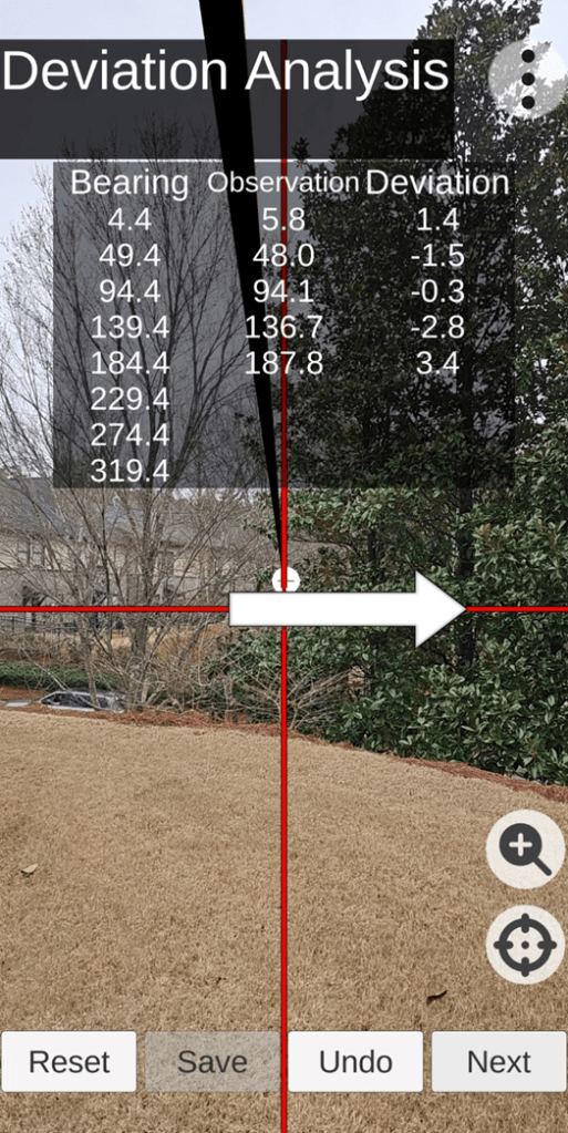
Situation: As indicated by the previous image, the user has progressed clockwise and captured five (5) azimuth values. At this time, TruPath Compass indicates another clockwise rotation toward the next augmented reality target point – until all eight (8) deviation data points have been collected.
Situation: The preceding image indicates that the user has collected all eight (8) azimuth data points. The screen crosshairs are left – centered on the Augmented Reality target just measured (azimuth).
At this point, the user should click on the “Save” button to a) process the data collected, b) analyze the collected data – determining the compensation parameters for this test case [phone orientation], and c) save the results for future application. Now, the user can experience corrected azimuth readings using TruPath Compass.
Data Analysis:
The following data table presents the collected UNCOMPENSATED azimuth deviation data (yellow) and the associated deviation error (orange) for the one Android phone orientation (portrait) – for all three (3) tests.
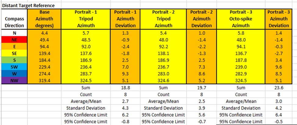
The Android/TruPath Compass app has done its best – yet residual (after calibration) azimuth deviation (error) persist – throughout the entire 360 degree range of measurement.
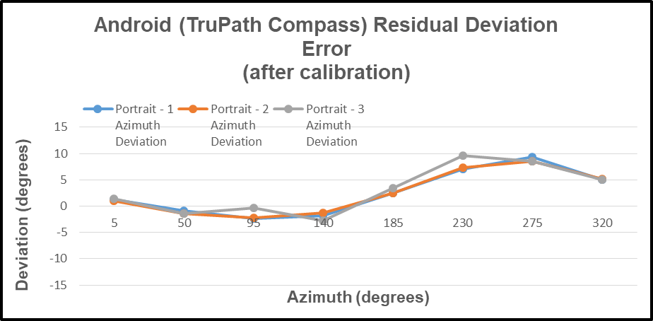
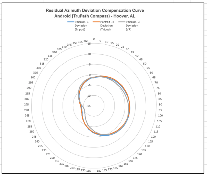
The following chart depicts the residual azimuth deviation (error) measured at each target point – for each test.
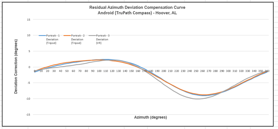
The “modeled” deviation curves (derived from the residual deviation error data) have been derived by the Android/TruPath Compass app; and these curves are presented below. The modeled residual azimuth deviation (compensation) curves are presented in two different formats to allow the reader to seriously consider the deviation error – as measured throughout the full 360 degree range of measurement.
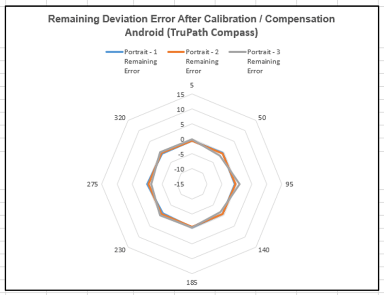
The compensated deviation errors (remaining azimuth errors after compensation) for the Android/TruPath Compass app are depicted below. Again, two display formats are provided to strengthen the perceived impact of the compensation method.
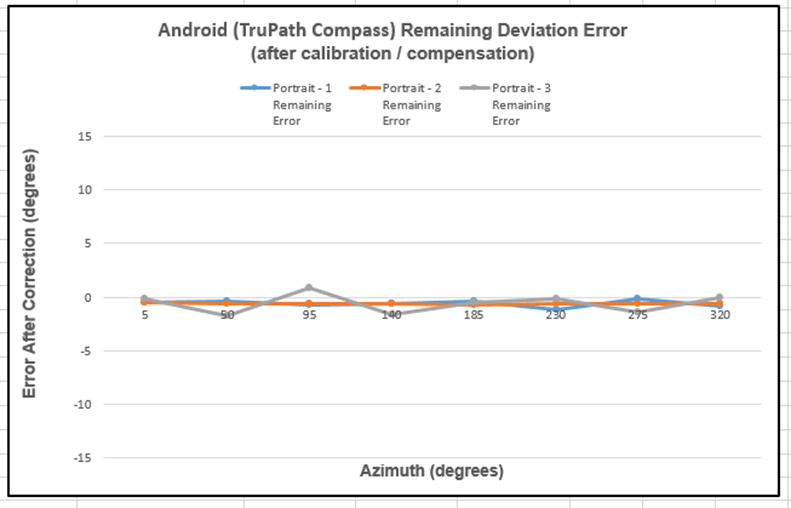
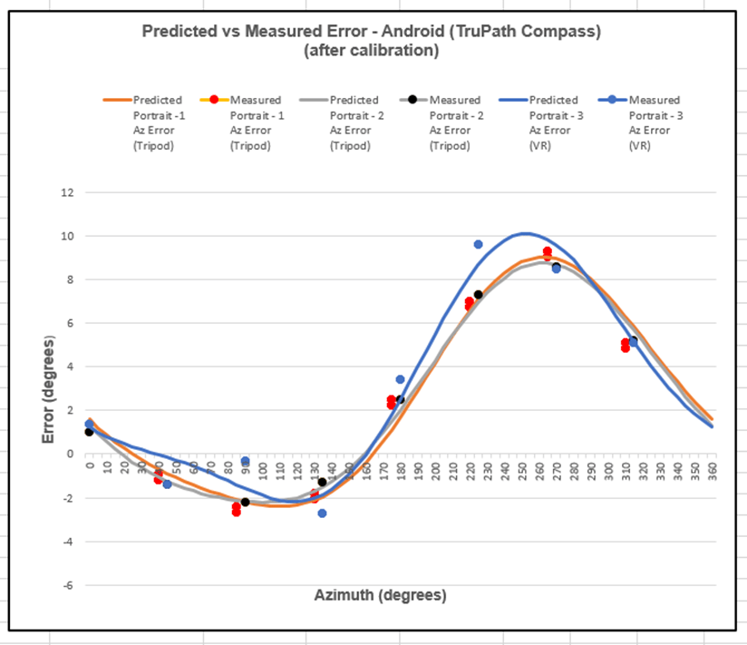
The predicted deviation errors are depicted (curves) in the following chart – along with the actual measured azimuth deviation (error) values (dots). The predicted deviation (error correction) curve is the negative of the deviation curve; and the compensation method proved quite effective.
Notes Regarding the Use of Distant Features (Targets)
- The greater the range between the observation point and the distant feature point; the more accurate the reference azimuth. If practical, choose a distant feature about 1/2 mile away from the observation point.
- TruPath Compass provides the capability to identify and locate (Lat/Long) the distant feature using the background map of the “compass” or home screen. Multiple map backgrounds are available.
- TruPath Compass provides the capability to edit the location coordinates of the identified distant feature – to refine the coordinates for increased accuracy – using land survey data or GPS data.
The following image depicts the use of TruPath Compass’ home screen to identify and locate a typical distant feature (orange marker symbol in the upper right of the screen) – the roof peak of a large building. The intended observation point is represented by the blue dot (GPS) in the center of the screen. The azimuth from the observation point to the distant target point was calculated to be 9.3 degrees – a good read by the TruPath Compass app without compensation being applied.
The following image depicts the use of the typical distant feature for collecting azimuth deviation data. In actual practice, the TruPath Compass user would a) center the screen crosshairs on the building’s highest point (center of building) and b) tap near the center of the screen to establish the reference azimuth (observation point to distant feature point) and simultaneously capture (collect) the first deviation data point.
Conclusions:
The Android/TruPath Compass app indicates the following measured residual (after calibration / uncompensated) azimuth deviation error ranges – at a 95% confidence limit for each test:
- Test 1: +6.2 < Residual Deviation Azimuth Error < -0.8 (degrees)
- Test 2: +5.6 < Residual Deviation Azimuth Error < -0.7 (degrees)
- Test 3: +6.4 < Residual Deviation Azimuth Error < -0.5 (degrees)
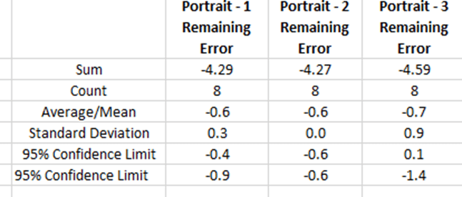
The compensated Android/TruPath Compass app results indicate the following remaining error ranges (after calibration / after compensation) – at a 95% confidence limit.
- Test 1: -0.4 < Residual Deviation Azimuth Error < -0.9 (degrees)
- Test 2: -0.6 < Residual Deviation Azimuth Error < -0.6 (degrees)
- Test 3: +0.1 < Residual Deviation Azimuth Error < -1.4 (degrees)
The Android/TruPath Compass app is easy-to-use in either handheld or tripod-mounted data collection modes.
- The TruPath Compass app (prototype) requires about 4 minutes to collect the measured azimuth deviation readings for each test case – very efficient.
- The TruPath Compass app (prototype) can be effectively used by an 11 year old child (the author’s granddaughter) – or more mature users.
The TruPath Compass app (prototype) has been demonstrated to compensate residual (after calibration) azimuth deviation errors in a very effective manner.
The TruPath Compass app (prototype) – repeatability – has been demonstrated particularly well when a) using a camera tripod equipped with an indexed azimuth ring and particularly well b) when using the app’s Augmented Reality targets.
The TruPath Compass app (once released) will have the potential to:
- Compensate residual (after calibration) azimuth deviation errors on the host smartphone (Android & iPhone).
- Determine the necessary compensation parameters for any third-party smartphone compass app (external device); and these compensation parameters will be made available for correcting the third-party compass app’s residual azimuth deviation errors.
- Determine the necessary compensation parameters for any third-party rangefinder compass (external device); and these compensation parameters will be made available for correcting the third-party rangefinder compass residual azimuth deviation errors.
- Determine the necessary compensation parameters for any third-party electronic compass (external device); and these compensation parameters will be made available for correcting the third-party electronic compass residual azimuth deviation errors.
Preview: The next blog post is planned to deal with the Android/TruPath Compass app compensating residual azimuth deviation errors in the middle of a crowded auto parking lot with lots of magnetic/electromagnetic influences.

Leave a comment