
Row, row, row your boat gently up / down the stream???
Purpose (RECALL): This blog post is created to help readers a) better understand electronic compass [smartphone or rangefinder] residual azimuth deviation errors b) quantify the errors, c) model the errors, d) compensate [correct] the errors, and e) influence the app vendors to apply the correction method within the affected smartphone app. Basically, we need to know (accurately) whether to go up / down the stream (path) we are traveling on.
Goal: The goal of this blog post is to demonstrate various mounting hardware configurations suitable for collecting azimuth deviation (error) data – necessary and sufficient for determining the compensation parameters for correcting compass azimuth errors.
Justification: Over the past several years, hundreds and thousands of smartphone users have complained (internet users’ forums) about their inability to use the compass apps – and rightly so. “Experts” have offered many “fixes” to resolve the issue; yet smartphone compass apps (all) have remained notoriously inaccurate.
Hypothesis: After recognizing a problem (error), if the error can be predicted, the error can be corrected.
Problem Statement: How can smartphone compass azimuth error be predicted (quantified / modeled) and then be compensated (corrected) in real world situations?
Solution Characteristics: In order for smartphone compass azimuth error to be compensated (corrected), the following statements are true.
- The error must be quantified – throughout the entire 360 degree range of measurement – in a manner that adds minimum cost to the user in terms of a) out-of-pocket expense, b) time and effort, and c) investment in education and/or training. This means that descriptive data must be collected to quantify the error.
- Manufacturer’s recommended compass calibration procedures must be factored in (and applied) to account for the “hard iron” and “soft iron” effects attributed by the materials and component(s) arrangements within the smartphone itself. The smartphone compass azimuth error to be compensated is the residual (after calibration) error resulting from environmental magnetic/electromagnetic influences – external to the smartphone itself.
- The deviation data collected about the compass azimuth error must be “modeled” in such a way that the predicted error can be “added back” (subtracted) from the original erroneous azimuth readings to compensate (correct) the error(s) – in a repeatable and reliable manner over the entire 360 degree range of measurement – within the local environment – over a wide (Latitude) geographic area.
Solution: The TruPath Compass smartphone app exhibits all the positive solution characteristics stated above.
Background:
This post depicts multiple mounting configurations of the new Android / TruPath Compass app (prototype) and various smartphone/compass app and laser rangefinder “external” device combinations. Each external device combination illustrates a separate and unique hardware setup configuration. These mounting configurations support the repeatability and reliability of the TruPath Compass app to compensate (correct) residual compass azimuth error for any electronic compass (smartphone/compass app, laser rangefinders, electronic compass, etc.).
- The selected Birmingham, AL demonstration site has a strong magnetic/ electromagnetic field influencing the earth’s magnetic field – and thus, the smartphone/rangefinder electronic compass.
- A small demonstration range was prepared for demonstrating four (4) separate and distinct device hardware configurations – necessary and sufficient for collecting azimuth deviation (error) data.
- Handheld configurations
- Tripod configurations
- The simulated data collection and data processing operation are illustrated.
- A reference azimuth (a known base direction) could be established from which to incrementally advance to other (sequential) known offset azimuths (45 degree increments, throughout a full 360 degree range of measurement). Although the True North direction was used as the reference direction for these demonstrations – for convenience of the reader, TruPath Compass does NOT require the use of True North as the reference azimuth (starting point) for azimuth data collection.
- Quantified azimuth error data (the difference between the known azimuth and the measured azimuth) could be collected – a total of eight (8) measurements. Using TruPath Compass, the total time required to collect the azimuth error measurements has been demonstrated to require less than 4 minutes per acquisition event – typical.
The data collection equipment and procedures used for all four (4) demonstrations would be identical to those used at the original Birmingham, AL test site for several prior posts. Refer to the original post/page at http://www.tru-path.org.
- True North (reference direction) can be established (staked out) based on the sun position (solar azimuth) relative to the observer’s (geographic) location on the date/time the tests were performed – a correct, defendable, and independent reference direction.
- A distant feature (target) location can be used to establish a reference direction (azimuth) relative to an observer’s location based on land survey, map, or GPS coordinate data.
- The Android/TruPath Compass app (and the external device app) should both be set to indicate azimuths relative to True North.
- The Android smartphone (sensors) and the external device (sensors) should be re-calibrated prior to initiating data collection.
Recall:
- Residual (after calibration) compass deviation error persists and its magnitude varies throughout the entire 360 degree range of measurement.
- Compensation of residual (after calibration) azimuth deviation error is device specific.
Site Characteristics – Birmingham, AL

The Birmingham, AL site is in an urban environment with strong magnetic/electromagnetic influences including:
- An electric power distribution station is located adjacent to eight (8) townhomes.
- At least eight operating heating/cooling (heat pump) units of 3 to 4 ton capacity – aligned North/South are within 50 feet of the test site (East side).
- An active highway – aligned North/South is within 150 feet of the test site (West side).
The observer’s location was staked out within sighting distance of a vertical (pole) target used to cast a good shadow (sun shadow). The shadow of the vertical stake was used to establish the azimuth of the sun – and thus, the azimuth (direction) to True North – as facilitated by the TruPath Compass app. Refer to the following image.
Observer Location (GPS)
- Latitude: 33.4118433
- Longitude: -86.7178023
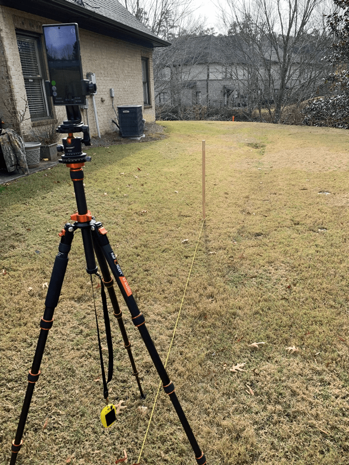
Smartphone in portrait orientation
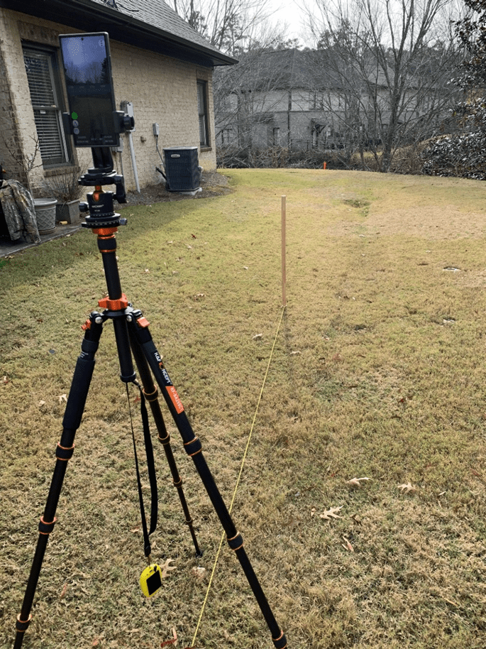
The tripod was capable of mounting a smartphone in either a portrait, landscape, or horizontal orientation. For these observations, only the portrait orientation was used – a) sufficient for demonstrating the mounting of various devices and b) without overwhelming the reader with voluminous repetitive information. An external GPS unit (BadElf Surveyor – yellow) was used to increase accuracy of both the observer and the distant target geographic location.
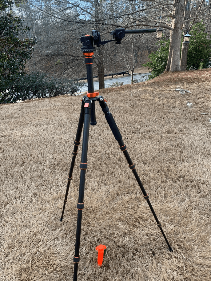
Smartphone in horizontal orientation
The tripod features an azimuth ring for mechanically (reliably) controlling the azimuth direction of the smartphone – no sighting error involved.
Camera Tripod with Azimuth Ring
From the observer’s location (tripod), a reference azimuth (True North) was established (staked out) using the sun’s position (solar azimuth) as a basis – as previously mentioned and demonstrated in previous blog posts.
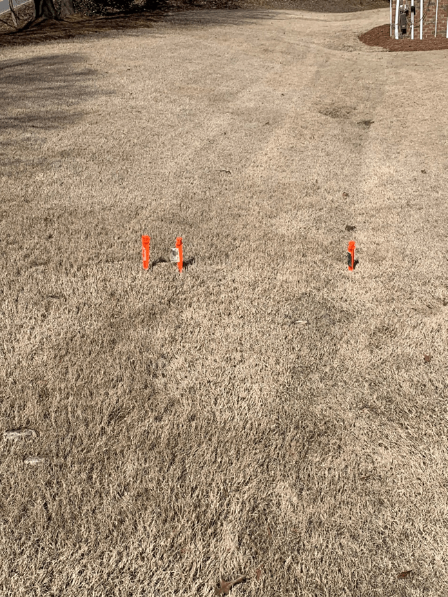
Distant Feature (target) Stakes
In the preceding image, the right-most stake (distant feature) indicates the True North azimuth from the observer’s location. The central-most stake indicates an azimuth of 355 degrees; while the left-most stake indicates an azimuth of 354 degrees as seen from the observer’s location. The central-most and left-most stakes were used (casually) to check azimuth readings using the TruPath Compass – the author’s choice to check compass calibration and error compensation.
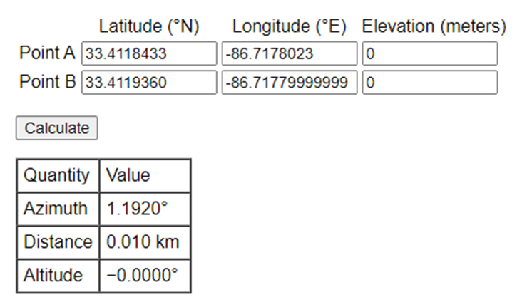
Right-most Stake Location (GPS)
- Latitude: 33.4119360
- Longitude: -86.7177999
Referring to the following table, the azimuth between the observation point (Point A) and the distant feature (target) point (Point B) was calculated to be 1.192 degrees – using a 64 bit computer and double precision math. When using the smartphone operating system with its inherent precision, the author might expect to experience somewhat less in terms of calculation accuracy.
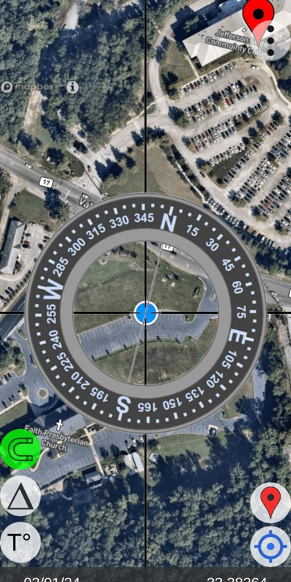
Moving along, the following image depicts the author’s first calibration/compensation check. Notice that TruPath Compass allowed the author to place (geo-locate) a marker on the map background corresponding to the location of the left-most (True North) target (stake). The marker can be placed on the map background using a Pan/Zoom capability; and that placement can be edited using either survey coordinates or GPS coordinates. The image indicates that the target is placed to give a reference True North azimuth from the observer’s location (the blue dot – a “current” GPS location).
The “red” vertical bar directly below the “N” character (True North) label indicates that TruPath Compass’ compensation is “ON” – indicated, as well, by the green (upper case delta symbol) button along the lower left side of the screen. The width/thickness of the red bar indicates the magnitude of the error compensation. The algebraic sign of the compensation value is indicated (depending on which side of the vertical screen alignment line the red bar lies) – left side (negative)/right side (positive). The signed numeric value of the compensation angle is shown at the bottom of the image – indicated by the lower case delta symbol (-1.3 degrees).
Note: The horizontal “horseshoe” button (lower left side of screen) is “green” indicating that the state of compass calibration is “good”.
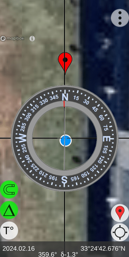
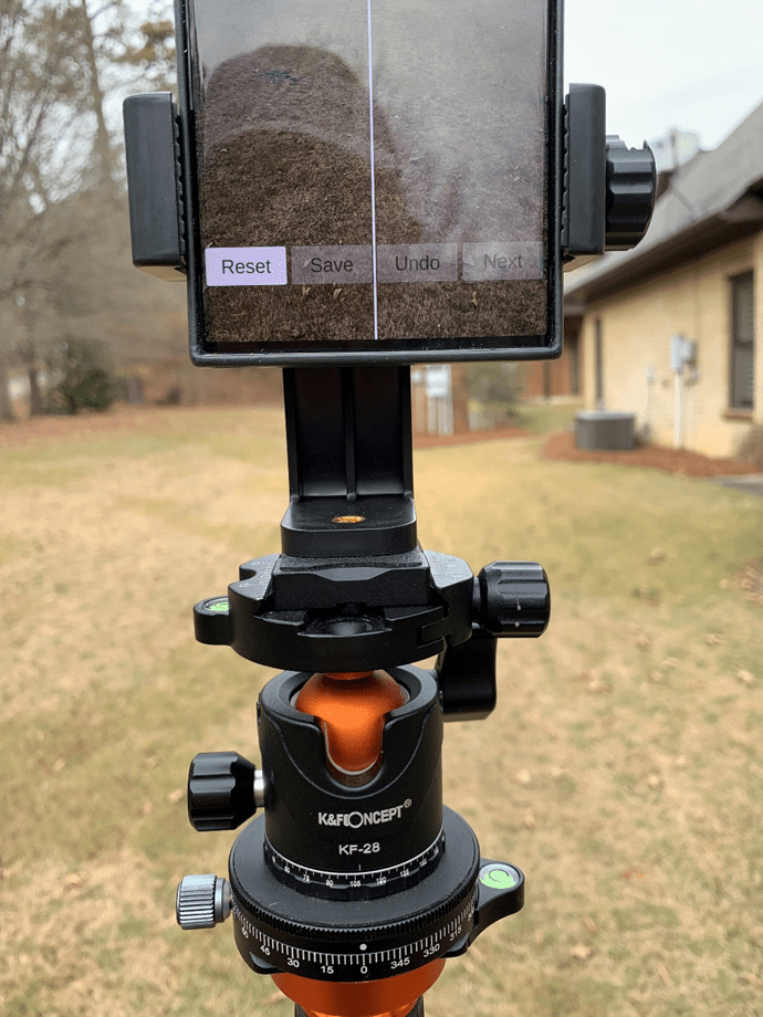
TruPath Compass “Home” Screen
The following image depicts the author’s second calibration/compensation check using the TruPath Compass’ virtual reality camera display (Live View – accessed via the Menu button shown in the upper-right corner of the screen. Again, the author can be satisfied that the compass calibration is operating well. Notice that in this image, the compensation is turned “OFF” – as indicated by a “white” compensation button and by a compensation magnitude of zero (0 degrees) at the bottom of the image.
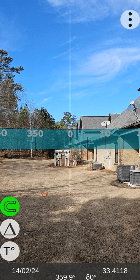
TruPath Compass “Live View” Screen
Faster, Better, Cheaper Azimuth Deviation (error) Data Collection
Typically, for collecting azimuth deviation data, the following attributes apply:
- Effort: The time required to collect azimuth deviation data is less than 4 minutes – for each orientation (portrait, landscape, or horizontal) of the smartphone.
- Circumstances:
- On sunny days, take advantage of the shadow of a vertical object (wooden stake, light poles, edge of building, standing person, etc.) to establish a base (reference) azimuth – TruPath Compass’ determination of the sun’s azimuth (to obtain unquestionable accuracy).
- On cloudy days, establish a base (reference) azimuth with a “distant feature” using TruPath Compass’ background map. The geographical location of the distant feature can be edited (using either land survey, map, or GPS coordinates) to improve accuracy.
- Flexibility/ Accuracy/Repeatability:
- Use TruPath Compass’ augmented reality targets to collect azimuth deviation (error) data – requires user sighting of the target – usually in a faster handheld mode of operation.
- Use a camera tripod (with azimuth ring) to collect azimuth deviation (error) data – mechanically traversing clockwise from the base (reference) azimuth in equal 45 degree increments – more steady and more accurate.
- Operation: (general use or collecting azimuth deviation data)
- Handheld
- Tripod
When collecting azimuth deviation data, TruPath Compass provides a “setup” screen that allows the user to specify the circumstances under which the azimuth deviation data will be collected. Refer to the following image.

Setup Screen – TruPath Compass
Alternative Operating Modes
For general use, and for collecting azimuth deviation data, TruPath Compass can be operated in two convenient operating modes – handheld and tripod mounted.
Handheld Operation
The mounting equipment can be obtained easily (Amazon) and economically.
Tripod Operation
The basic idea is to obtain azimuth deviation (error) data of a quality sufficient to model the error pattern and produce the “deviation compensation curve(s)”; and the process should be repeatable.
Compensating Compass Errors – “External” Devices
Samsung S23 (TruPath Compass) & iPhone (Compass)
It may be convenient for the user to evaluate the accuracy (or lack thereof) of any of several smartphone compass apps – operating as an external device. It is important that the TruPath Compass app and the third party smartphone compass app be operated such that the primary axis of orientation for each smartphone be parallel to the other – in order to obtain valid azimuth deviation data from the third party smartphone app.
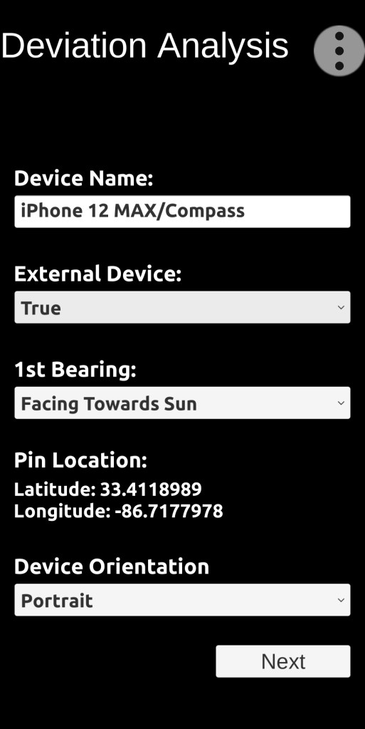
TruPath Compass Setup Screen
Alternative Operating Modes
For general use, and for collecting azimuth deviation data, TruPath Compass can be operated in two convenient operating modes – handheld and tripod mounted.
Note: Third party smartphone compass apps can be operated in any of several orientations (portrait, landscape, or horizontal).
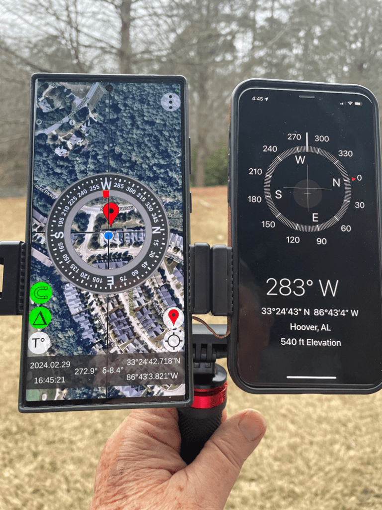
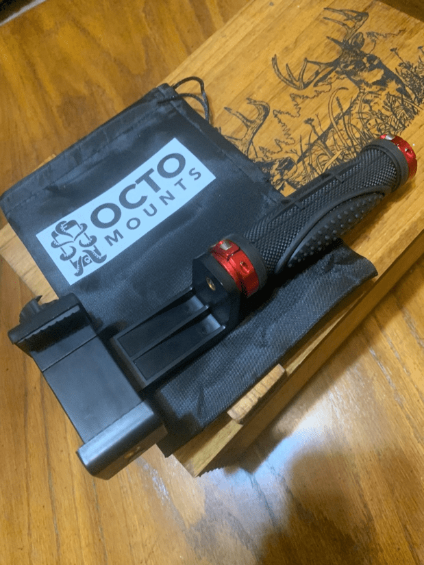
External Device: iPhone/Compass App – Handheld Mount
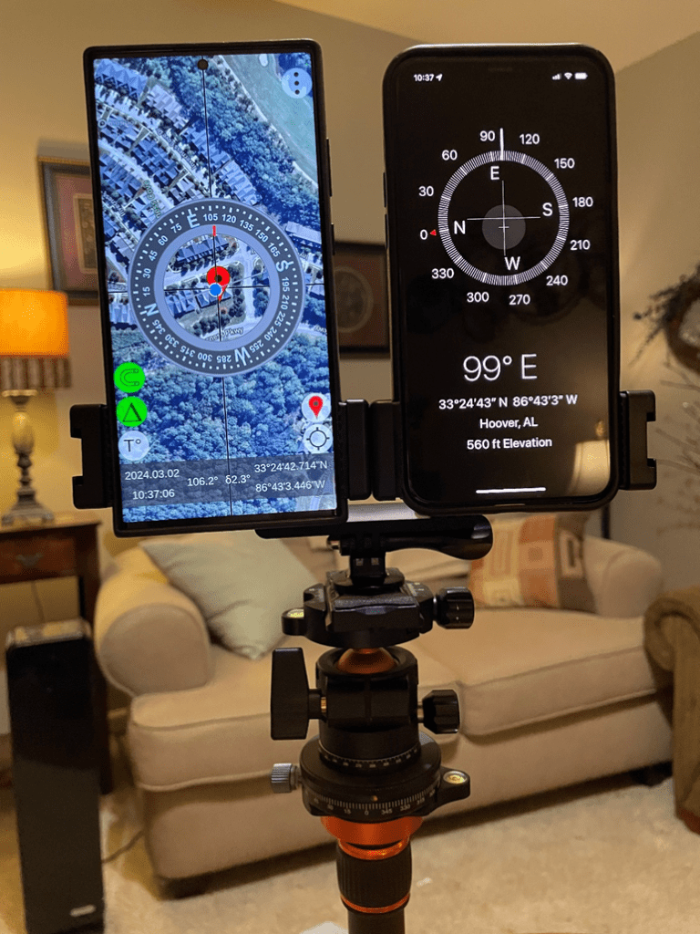
External Device: iPhone/Compass App – Tripod Mount
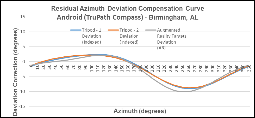
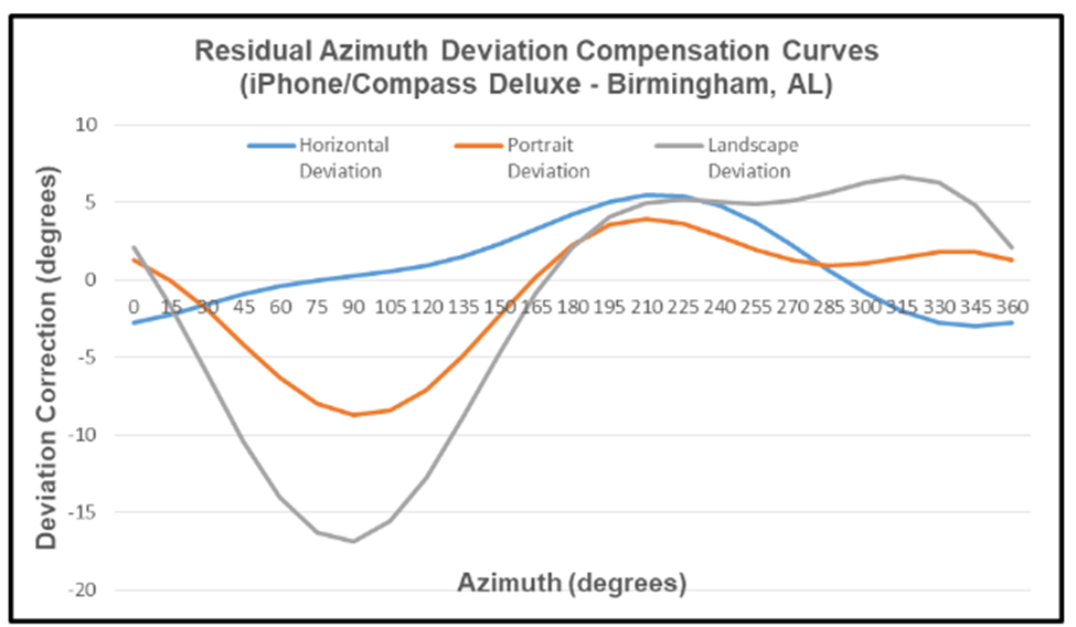
An example of the deviation compensation curves for an iPhone compass app follows.
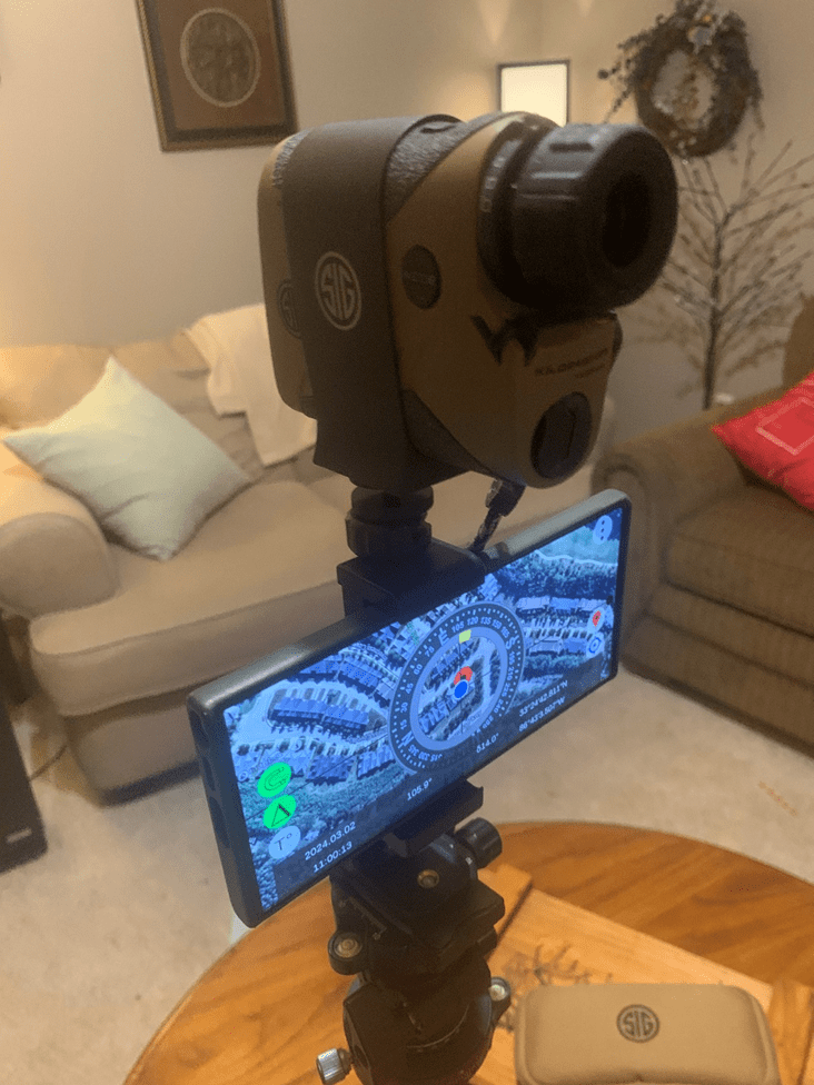
Laser Rangefinder – Samsung S23 (TruPath Compass) & Sig Sauer KILO2400 ABS
It may be convenient for the user to evaluate the accuracy (or lack thereof) of any of several laser rangefinders (with compass) – operating as an external device. It is important that the TruPath Compass app and the rangefinder be operated such that the primary axis of orientation for each device is parallel to the other – in order to obtain valid azimuth deviation data from the third party smartphone app.

TruPath Compass Setup Screen
Alternative Operating Modes
For general use, and for collecting azimuth deviation data, TruPath Compass can be operated in two convenient operating modes – handheld and tripod mounted.
Note: Of the rangefinders evaluated, the predominant operating orientation is “portrait”.
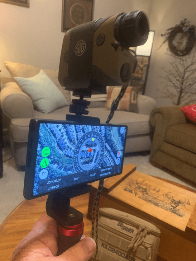
External Device: Sig Sauer KILO2400 ABS Rangefinder – Handheld Mount
External Device: Sig Sauer KILO2400 ABS Rangefinder – Tripod Mount
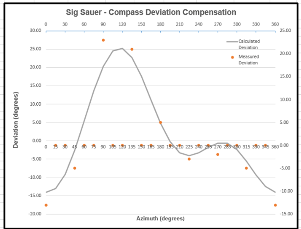
An example of the deviation compensation curve for the Sig Sauer KILO2400 ABS rangefinder (with compass) follows.
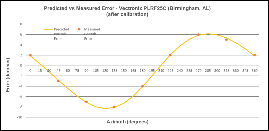
Laser Rangefinder – Samsung S23 (TruPath Compass) & Vectronix PLRF-25C
Again, it may be convenient for the user to evaluate the accuracy (or lack thereof) of any of several laser rangefinders (with compass) – operating as an external device. It is important that the TruPath Compass app and the rangefinder be operated such that the primary axis of orientation for each device is parallel to the other – in order to obtain valid azimuth deviation data from the third party smartphone app.
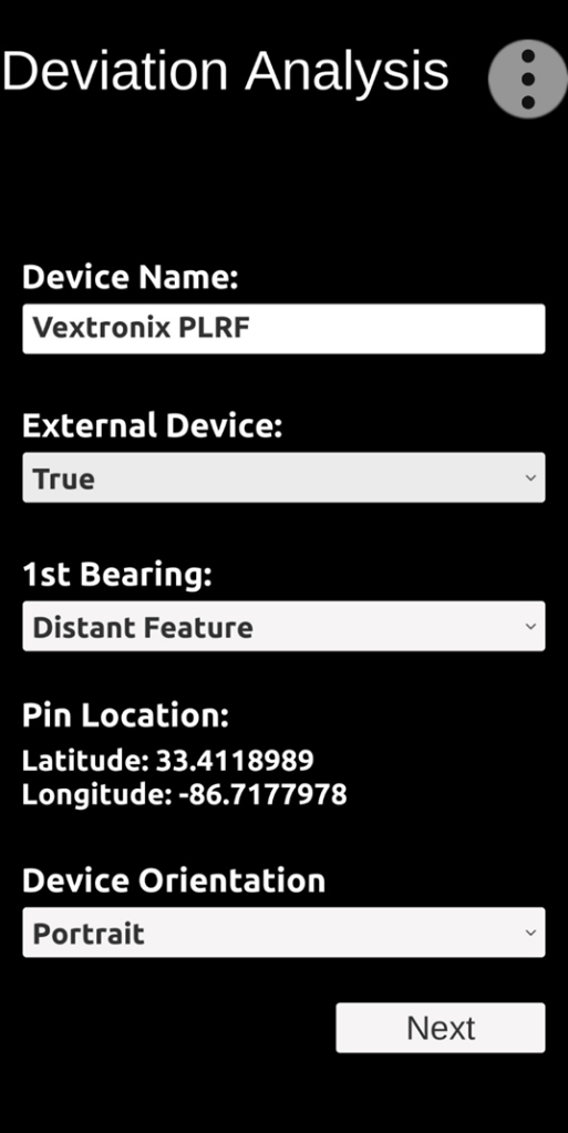
TruPath Compass Setup Screen
Note: Of the rangefinders evaluated, the predominant operating orientation is “portrait
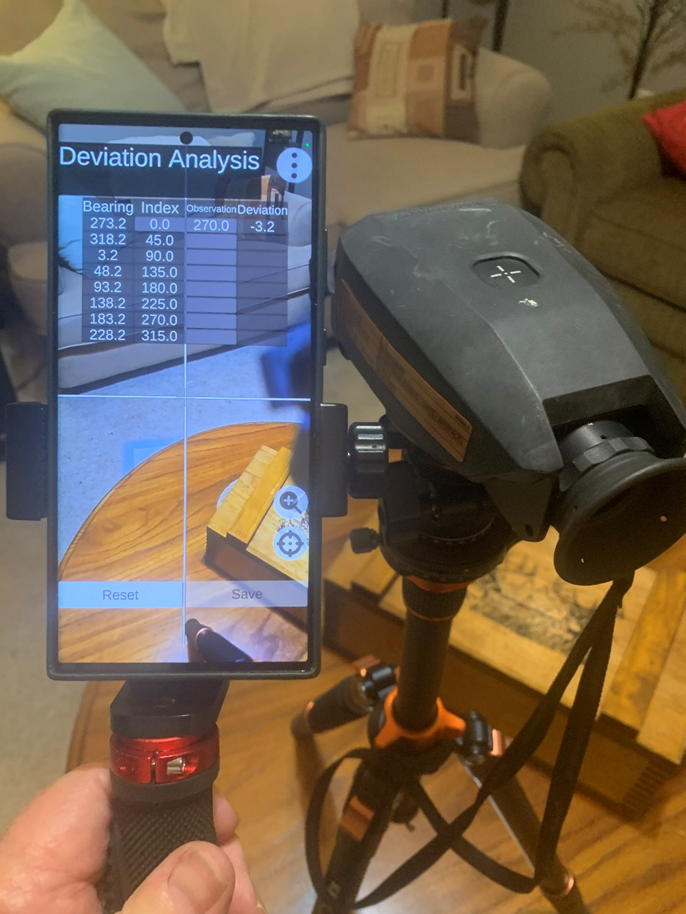
External Device: Vectronix PLRF-25C Rangefinder – Tripod Mount
Note: Due to the weight of the Vectronix rangefinder, the author does not recommend handheld operation for collecting azimuth deviation data.
An example of the deviation compensation curve for the Vectronix PLRF-25C rangefinder (with compass) follows.
Clarification: Using the Distant Feature (target) to Establish a Reference Azimuth
The following image depicts the use of TruPath Compass’ home screen to identify and locate a typical distant feature (orange marker symbol in the upper right of the screen) – the roof peak of a large building. The intended observation point is represented by the blue dot (GPS) in the center of the screen. The azimuth from the observation point to the distant target point was calculated to be 9.3 degrees – a good read by the TruPath Compass app.
The following image depicts the use of the typical distant feature for collecting azimuth deviation data. In actual practice, the TruPath Compass user would a) center the screen crosshairs on the building’s highest point (center of building) and b) tap near the center of the screen to establish the reference azimuth (observation point to distant feature point) and simultaneously capture (collect) the first deviation data point.

Conclusions:
The Android/TruPath Compass app is easy-to-use in either handheld or tripod-mounted data collection modes.
- The TruPath Compass app (prototype) requires about 4 minutes to collect the measured azimuth deviation readings for each test case – very efficient.
- The TruPath Compass app (prototype) can be effectively used by an 11 year old child (the author’s granddaughter) – or more mature users.
The TruPath Compass app (prototype) has been demonstrated to compensate residual (after calibration) azimuth deviation errors in a very effective manner.
The TruPath Compass app (prototype) – repeatability – has been demonstrated particularly well when a) using a camera tripod equipped with an indexed azimuth ring and particularly well b) when using the app’s Augmented Reality targets.
The TruPath Compass app (once released) will be capable of:
- Compensating residual (after calibration) azimuth deviation errors on the host smartphone (Android & iPhone).
- Determining the necessary compensation parameters for any third-party smartphone compass app (external device); and these compensation parameters will be made available for correcting the third-party compass app’s residual azimuth deviation errors.
- Determining the necessary compensation parameters for any third-party rangefinder compass (external device); and these compensation parameters will be made available for correcting the third-party rangefinder compass residual azimuth deviation errors.
- Determining the necessary compensation parameters for any third-party electronic compass (external device); and these compensation parameters will be made available for correcting the third-party electronic compass residual azimuth deviation errors.
Preview: The next blog post is planned to deal with the Android/TruPath Compass app compensating residual azimuth deviation errors in the middle of a crowded auto parking lot with lots of magnetic/electromagnetic influences.

Leave a comment